Question
Question: For the LCR circuit, shown here, the current is observed to lead the applied voltage. An additional ...
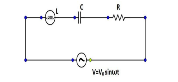
For the LCR circuit, shown here, the current is observed to lead the applied voltage. An additional capacitor C′, when joined with the capacitor C present in the circuit, makes the power factor of the circuit unity. The capacitor C′ must have been connected in:
(A) ω2L1−ω2LCparallel with C
(B) ω2L1−ω2LCseries with C
(C) (ω2LC−1)Cparallel with C
(D) (ω2LC−1)Cseries with C
Solution
Given that the power factor of the circuit is unity. The difference of impedance reactance and capacitive reactance is zero. So we need to compute their values and solve the equation to find the answer.
Formula Used: The formulae used in the solution are given here.
The impedance of circuit is given by Z=R2+(ωL−ωC1)2 where R is the resistance and C is the capacitance and ω=2πf where f is the frequency.
XL is impedance reactance and XC is capacitive reactance.
Complete Step by Step Solution: In general power is the capacity to do work. In the electrical domain, electrical power is the amount of electrical energy that can be transferred to some other form (heat, light etc.) per unit time. Mathematically it is the product of voltage drop across the element and current flowing through it. Considering first the DC circuits, having only DC voltage sources, the inductors and capacitors behave as short circuits and open circuits respectively in steady state.
Now coming to AC circuit, here both inductor and capacitor offer a certain amount of impedance given by:
XL=2πfL and XC=2πfC1.
The inductor of impedance L stores electrical energy in the form of magnetic energy and capacitor of capacitance C stores electrical energy in the form of electrostatic energy.
Neither of them dissipates it. Further, there is a phase shift between voltage and current.
The cosine of this phase difference is called electrical power factor. This factor (−1<cosφ<1 ) represents the fraction of the total power that is used to do the useful work. The other fraction of electrical power is stored in the form of magnetic energy or electrostatic energy in the inductor and capacitor respectively.
Given that, the current is observed to lead the applied voltage in the LCR circuit. An additional capacitor C′, when joined with the capacitor C present in the circuit, makes the power factor of the circuit unity.
Thus, cosφ=1.
cosφ=R2[ωL−ω(C+C′)1]R=1.
On solving the equation above, we get,
⇒ωL=ω(C+C′)1
The capacitor C′ must have magnitude:
C′=ω2L1−ω2LC
Adding capacitor of capacitance C' in parallel of C, the reactance will be:
XL−XC=ωL−ω(C+C′)1
Since, XL−XC=0,
ωL−ω(C+C′)1=0
⇒C′=ω2L1−C
Connecting the capacitors in parallel, C′=ω2L1−ω2LC
Hence the correct answer is Option A.
Note: The impedance of circuit is given by Z=R2+(ωL−ωC1)2 and the current lag voltage by tanφ=RXL−XC=RωL−ωC1
For the power factor to be one the current and voltage have to be in the same phase i.e. φ has to be zero.
Adding capacitor of capacitance C′ in series of C, the reactance will be
XL−XC=ωL−ω(C+C′)1
⇒ωL−ω(C+C′CC′)1
Which gives us,
⇒ω2LCC′=C+C′
The value of C′ when connected in series will be,
Thus, C′=ω2LC−1C.