Question
Question: For the circuit shown, with \({R_1}\)=1.0Ω, \({R_2}\)=2.0Ω, \({E_1}\)=2 V and \({E_2} = {E_3}\)=...
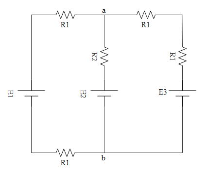
For the circuit shown, with R1=1.0Ω, R2=2.0Ω, E1=2 V and E2=E3=4 V, the potential difference between the points ′a′ and ′b′ is approximately (in V).
Solution
In order to find out the effective resistance we use series and parallel connection formulas. Similarly cells also can be connected in series and parallel. If cells are connected in series we have one formula to find the effective emf and if cells are connected in parallel we have another formula to find effective emf.
Formula used:
\eqalign{
& {R_s} = {R_1} + {R_2} + {R_3} + ......... \cr
& \dfrac{1}{{{R_P}}} = \dfrac{1}{{{R_1}}} + \dfrac{1}{{{R_2}}} + \dfrac{1}{{{R_3}}} + ....... \cr}
Eeff=RX1+RY1+RZ1RXEX+RYEY+RZEZ
Complete answer:
Rate of flow of charge is known as current. A material which allows current to pass through it is known as a conductor. No conductor will be perfect. It will have some resistance. The property to hinder the flow of current is called resistance and a device which does that is known as a resistor.
If the same current is passing through all resistors then we tell those are connected in series. If potential difference is the same for all resistors then those resistors are told to be in parallel.
The circuit is given below
When resistors are connected in series then effective resistance is Rs=R1+R2+R3+.........
When resistors are connected in parallel effective resistance will be RP1=R11+R21+R31+.......

If we clearly observe the above circuit, in the right side loop, both R1 resistors are in series.
So the effective resistance will be
\eqalign{
& {R_s} = {R_1} + {R_2} + {R_3} + ......... \cr
& \Rightarrow {R_s} = {R_1} + {R_1} \cr
& \Rightarrow {R_s} = 2{R_1} \cr}
In the left side loop too, both R1 resistors are in series.
So the effective resistance will be
\eqalign{
& {R_s} = {R_1} + {R_2} + {R_3} + ......... \cr
& \Rightarrow {R_s} = {R_1} + {R_1} \cr
& \Rightarrow {R_s} = 2{R_1} \cr}
Now 2R1 can be considered as resistance adjacent to E1 and R2 can be considered as resistance adjacent to E2 and 2R1 can be considered as resistance adjacent to E3. The effective circuit is shown below.
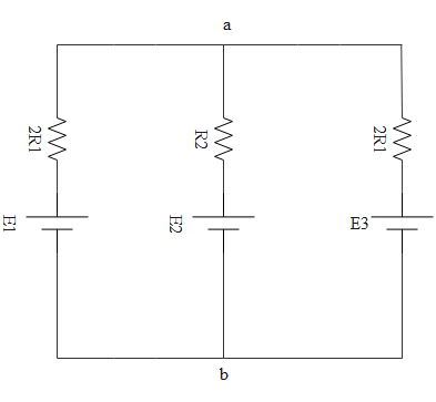
So all 3 cells are in parallel with polarities at one side, no cell is reversed. So the effective emf will be
Eeff=RX1+RY1+RZ1RXEX+RYEY+RZEZ
Where resistors RX, RY, RZ are in parallel condition too. They are adjacent to respective resistors.
\eqalign{
& {E_{eff}} = \dfrac{{\dfrac{{{E_1}}}{{2{R_1}}} + \dfrac{{{E_2}}}{{{R_2}}} + \dfrac{{{E_3}}}{{2{R_1}}}}}{{\dfrac{1}{{2{R_1}}} + \dfrac{1}{{{R_2}}} + \dfrac{1}{{2{R_1}}}}} \cr
& \Rightarrow {E_{eff}} = \dfrac{{\dfrac{2}{2} + \dfrac{4}{2} + \dfrac{4}{2}}}{{\dfrac{1}{2} + \dfrac{1}{2} + \dfrac{1}{2}}} \cr
& \Rightarrow {E_{eff}} = \dfrac{{10}}{3} \cr
& \Rightarrow {E_{eff}} = 3.3V \cr}
Hence the potential difference across terminals a and b will be 3.3 volts
Note:
The parallel effective emf formula which we had applied was actually derived for the case to find effective emf when cells with internal emf’s are connected in parallel. Here also we can use the same formula by considering the resistances adjacent to cells as the internal resistances.