Question
Question: For the circuit shown in the figure, 
A) Resistance R=46Ω
B) Current through 20Ω resistance is 0.1A
C) Potential difference across the middle resistance is 2V
D) All of the above are true
Solution
The last three resistors in the figure are connected in parallel. The equivalent resistance of these resistors is calculated and is considered as a single resistor. This resistor is connected in series with the first resistor. From the formulas for series and parallel connections of resistors, we can calculate the unknown resistance. To calculate the current through the last resistor and the potential difference across the middle resistor, we proceed by following Kirchhoff’s rules.
Complete step by step answer:
Firstly, let us redraw the circuit by naming the components according to our comfortability.
Let us name the resistors as
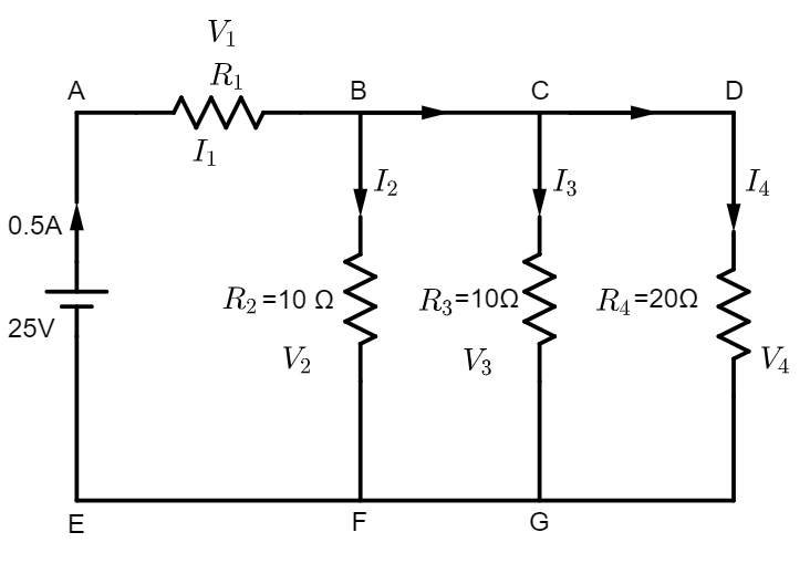
R1 = unknown, R2=10Ω, R3=10Ω and R4=20Ω
Let the currents flowing through resistors R1,R2,R3 and R4 be I1,I2,I3 and I4, respectively.
Let the potential differences across the resistors R1,R2,R3 and R4 be V1,V2,V3 and V4, respectively.
It is given that emf=25V and I1=0.5A. We have to calculate the other parameters to see if the options given with the question are right.
From the figure, it is clear that R2,R3 and R4 are connected in parallel. Let the equivalent resistance of these resistances be Rp. Clearly, Rp is given by
Rp1=R21+R31+R41=101+101+201=205=41⇒Rp=4Ω
Now, R1 and Rp are connected in series. Let us consider the circuit to be a circuit with a single resistor R1+Rp. To obtain the value of R1, we can apply Ohm’s law as follows.
R1+Rp=I1V1=0.525=50Ω⇒R1+4Ω=50Ω⇒R1=46Ω
Therefore, option A is correct.
Let us check the other options too.
To proceed, we have to apply Kirchhoff’s rules to find the current and potential difference through each resistor.
Kirchhoff’s current rule (KCL) says that the algebraic sum of the currents meeting at a junction in a closed electric circuit is zero. It says that
∑I=0
Applying this rule in our circuit, we have I1=I2+(I1−I2) at node B and (I1−I2)=I3+(I1−I2−I3) at node C. Clearly, I4=I1−I2−I3. Let this be equation 1.
Kirchhoff’s voltage rule (KVL) says that the algebraic sum of change in potential around any closed path of an electric circuit (or closed loop) involving resistors and cells in the loop is zero. It says that ∑emf+∑IR=0
Applying this rule in closed loop ABFE, we have
−25+I1R1+I2R2=0⇒−25+(0.5)(46)+I2(10)=0⇒10I2=2⇒I2=0.2A
Again, applying KVL to the loop ABCGFE, we have
−25+I1R1+I3R3=0⇒−25+(0.5)(10)+I3(10)=0⇒10I3=2⇒I3=102=0.2A
Substituting the values of I2 and I3 in equation 1, we have
I4=I1−I2−I3=0.5−0.2−0.2=0.1A
Therefore, the current through the resistor 20Ω is equal to 0.1A. Hence, option B is also correct. Now, let us see if the third option is correct. It says that the potential difference across the middle resistor (R1 or R2) is equal to 2V.
Let us apply Ohm’s law to any of the middle resistors to obtain the value of potential difference across it.
V=IR⇒V2=V3=0.2A×10Ω=2V
The third option C is also correct. Therefore, option D is the correct option which says that all the statements mentioned in the options are correct.
Note:
Kirchhoff’s rules follow sign convention. To make it easy, in KCL, the current flowing towards a node is taken as positive and the current flowing away from the node is taken as negative. In KVL, while traversing a loop, if a negative pole of the cell is encountered first, then its emf is negative, otherwise positive.