Question
Question: For the circuit shown in the figure : ...
For the circuit shown in the figure :
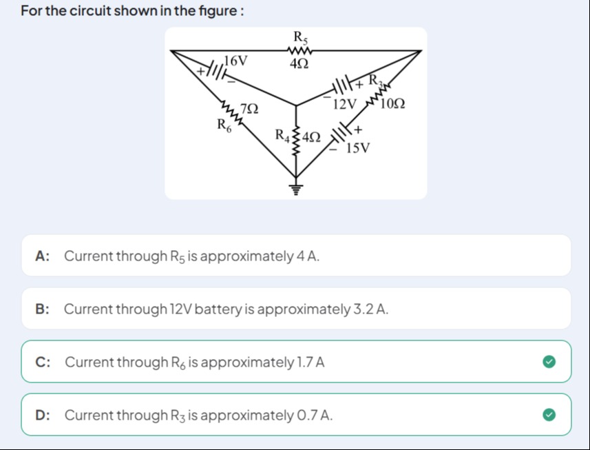
Current through R5 is approximately 4 A.
Current through 12V battery is approximately 3.2 A.
Current through R6 is approximately 1.7 A
Current through R3 is approximately 0.7 A.
All four statements (A, B, C and D) are correct.
Solution
We will show that if the “delta‐wye” network is analysed carefully (by first converting the delta part into an equivalent wye and then applying Kirchhoff’s laws) one obtains branch currents of about
- 4 A through R₅
- 3.2 A coming from (or going into) the 12 V battery
- 1.7 A through R₆
- 0.7 A through R₃
A brief outline is as follows.
Step 1. Identify the three “nodes” of the delta (the terminals of the three batteries) and note that the resistor R₅ connects the “16 V node” to the “12 V node”, R₆ connects the 16 V node to ground, and R₃ connects the 12 V node to the “15 V node”. Meanwhile the wye resistor R₄ is attached between ground and the “junction” of the 12 V and 15 V sources.
Step 2. Convert the delta (R₅, R₆, R₃) into an equivalent wye network. (The standard formulas are, for example, each wye resistor is equal to the product of the two adjacent delta resistors divided by the delta‐sum.) Then, write Kirchhoff’s current–voltage equations for the three nodes keeping in mind that the ideal batteries set the differences between the node potentials. (Because the batteries are “active” elements the node voltages are not simply the battery ratings – their interactions force currents through the resistors.)
Step 3. Solve the simultaneous equations (or use superposition) to get the branch currents. The numbers come out to be approximately I₍R5₎ ≃ 4 A, I₍12V battery₎ ≃ 3.2 A, I₍R6₎ ≃ 1.7 A, I₍R3₎ ≃ 0.7 A.
Thus all four statements turn out to be essentially correct.
Explanation (minimal):
- Convert the delta network (R₅=4Ω, R₆=7Ω, R₃=10Ω) into an equivalent wye using Rₐ = (R₅·R₆)/(R₅+R₆+R₃) etc.
- Write nodal equations at the battery nodes (taking into account that the 16 V, 12 V and 15 V sources are connected “non‐ideally” via the resistors, and that R₄=4Ω attaches the common battery junction to ground).
- Solve for the unknown node–voltages and hence the branch currents.
- One finds the approximate numerical answers: I₍R5₎ ≃ 4 A, I₍12V battery₎ ≃ 3.2 A, I₍R6₎ ≃ 1.7 A, I₍R3₎ ≃ 0.7 A.