Question
Question: For series LCR AC circuits shown in figure, the readings of and are the same \({V_2}\) and \({V_3}\)...
For series LCR AC circuits shown in figure, the readings of and are the same V2 and V3 each equal to 100V. Then
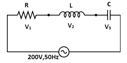
A) The reading V1 is 200V
B) The reading of V2 is 0
C) The circuit is in resonant mode
D) The inductive and capacitive reactance are equal.
Solution
Hint
For a series LCR circuit, the equation of voltage is given by V=V12+(V2−V3)2. Here, V2 and V3 are equal, so V=V12. Substitute the voltage of the cell and simplify to get the voltage across the resistor.
Complete step-by-step solution
The resistor, capacitor and the inductor are connected in series. For a series LRC circuit from the phasor diagram we know that,
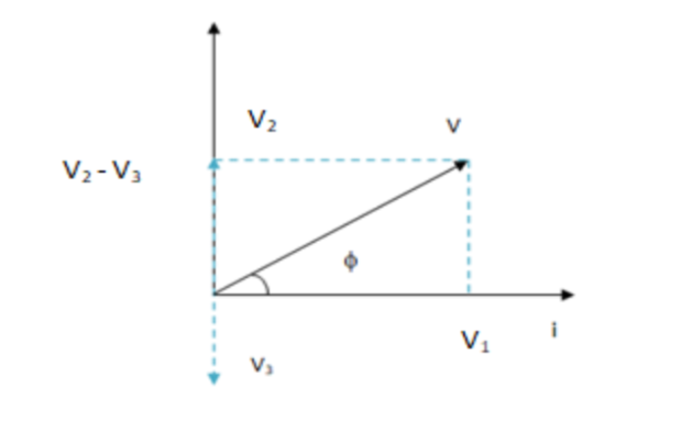
V=V12+(V2−V3)2
Where, V1,V2 and V3 are voltages of resistor, inductor and capacitor respectively.
Given in the question that,
V2=V3=100V
V=200V
Substitute the voltage readings of capacitor and inductor in the equation of voltage.
200=V12+(100−100)2
200=V12+0
V12=2002
V1=100V
Hence, the value of voltage across the resistor is V1=100V.
The correct option above is (A)
Note
For a series LCR circuit, Equation of current:
i=i0sin(ωt±ϕ)
Impedance of the circuit is given by:
Z=R2+(XL−XC)2
Phase difference is given by:
tanϕ=VRVL−VC
At resonance, the circuit behaves as a resistive circuit and the whole applied voltage appears across the resistance. The average power and the apparent power are equal at resonance. If the net reactance is inductive, the circuit behaves as an LR circuit. Similarly, when net reactance is capacitive then the circuit behaves as a CR circuit.