Question
Question: For circuits shown in fig (a) and fig (b). ,the ammeter reading would be- (A). \[1A\,\] in both ci...
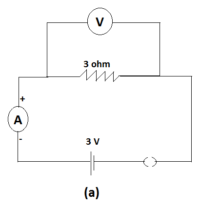
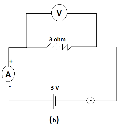
For circuits shown in fig (a) and fig (b). ,the ammeter reading would be-
(A). 1A in both circuits
(B). 0A in (a), 1A in (b).
(C). 1A in (a), 0A in (b)
(D). 0A in both the circuits
Solution
Using ohm’s law the value of current can be calculated by substituting the corresponding values. Also check whether the circuits are open or close as current only flows in closed circuits. The ammeter and voltmeter are used to determine the current and potential difference across two points respectively.
Formulas used:
R=IV
Complete answer:
An ammeter is a device which is used to detect the magnitude of current flowing in the circuit. A voltmeter is a device which is used to measure the potential difference between two points in a circuit.
In the fig (a)

The switch is open which means that the circuit is not complete. If the circuit is open no current can flow in it. Therefore the current here is zero. So the ammeter reading is zero.
In fig (b)

In this circuit, since the switch is closed, the circuit is complete, so current flows.
According to ohm’s law
R=IV
⇒V=IR - (1)
Here,
R is the resistance
I is the current
V is the potential difference
There is almost no potential drop on the ammeter as its resistance is negligible. While the potential drop on voltmeter is equal to the potential drop on the resistor as they are connected in parallel.
Using eq (1) In fig (b), we get,