Question
Question: Find \({V_A} - {V_B}\) in the given diagram. 
Solution
Here the two resistors connected to point B and the two resistors connected to point A make up two serial connections. These two serial connections then make up a parallel connection. At steady-state, no current will pass through the capacitor. So the potential difference across A and B can be obtained by determining the current through the two arms of the bridge arrangement.
Formulas used:
-The effective resistance in a series connection between two resistors is given by, Reff=R1+R2 where R1 and R2 are the resistances of the two resistors.
-The effective resistance in a parallel connection between two resistors is given by, Reff=R1+R2R1R2 where R1 and R2 are the resistances of the two resistors.
-Ohm’s law gives the current in a circuit as I=RV where V is the potential difference and R is the resistance offered to the flow of current.
Complete step by step solution:
Step 1: Sketch the given circuit diagram and mark the current through each arm.
Let the total current in the circuit be I . This current then splits into i1 and i2 to pass through two arms of the bridge arrangement of resistors. The voltage across the circuit is given to be V=12V .
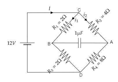
As seen from the above figure, R1=2Ω and R3=2Ω are connected in series. Also, R2=4Ω and R4=8Ω are connected in series.
The current through arm CB is i1 and the current through arm CA is i2 .
Step 2: Express the effective resistance offered by the circuit.
Now, the effective resistance across the left side of junctions C and D will be
Reff1=R1+R3 ------- (1)
Substituting for R1=2Ω and R3=2Ω in equation (1) we get, Reff1=2+2=4Ω .
Thus the effective resistance to the left of junctions C and D is Reff1=4Ω .
The effective resistance across the right side of junctions C and D will be
Reff2=R2+R4 ------- (2)
Substituting for R2=4Ω and R4=8Ω in equation (2) we get, Reff2=4+8=12Ω .
Thus the effective resistance to the right of junctions C and D is Reff2=12Ω .
At steady-state, no current will pass through the capacitor in the circuit so we can discard it.
Then as the two obtained effective resistances on either side of the junctions C and D form a parallel connection, the effective resistance of the entire circuit will be Reff=Reff1+Reff2Reff1Reff2 ------- (3)
Substituting for Reff1=4Ω and Reff2=12Ω in equation (3) we get, Reff=4+124×12=3Ω
Thus the effective resistance offered by the circuit is obtained to be Reff=3Ω .
Step 3: Express the total current in the circuit.
Ohm’s law gives the current in the given circuit as I=ReffV ------- (4)
Substituting for V=12V and Reff=3Ω in equation (4) we get, I=312=4A .
So the total current in the circuit will be I=4A .
Step 4: Express the current i1 and i2 based on Ohm’s law.
The current across arm CB will be the current across the effective resistance to the left of the junctions C and D i.e., i1=Reff1V ------- (5)
Substituting for V=12V and Reff1=4Ω in equation (5) we get, i1=412=3A
The current across arm CB is i1=3A .
The current across arm CA will be the current across the effective resistance to the right of the junctions C and D i.e., i2=Reff2V ------- (6)
Substituting for V=12V and Reff2=12Ω in equation (6) we get, i2=1212=1A
The current across arm CA is i2=1A .
Step 5: Express the potential at A and B to obtain the required potential difference.
Now the potential at A will be the potential drop across the resistor R2 .
ie., VA=i2R2 --------- (7)
Substituting for i2=1A and R2=4Ω in equation (7) we get, the potential at A as VA=1×4=4V.
Similarly, the potential at B will be the potential drop across the resistor R1 .
ie., VB=i1R1 --------- (8)
Substituting for i1=3A and R1=2Ω in equation (8) we get, the potential at B as VB=3×2=6V.
Then the potential difference between point A and B will be VA−VB=4−6=−2V .
∴ the magnitude of the required potential difference is VA−VB=2V .
Note: In a parallel connection of two resistors, the potential difference across the two resistors will be the same, however, the current through the two resistors will be different. This concept is used in step 4 to express the currents i1 and i2 through the two arms CB and CA of the bridge arrangement of the resistors.