Question
Question: Find the minimum load resistance which can be used for the zener diode as shown in figure. Given, \[...
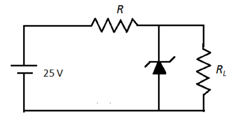
Find the minimum load resistance which can be used for the zener diode as shown in figure. Given, VZ=10V, RZ=0Ω, R=450Ω, Iz(min)=2mAand Iz(max)=60mA.
(A) 0Ω
(B) 333.3Ω
(C) 31.95Ω
(D) 319.5Ω
Solution
Calculate the total current in the circuit using KVL. This current divides at the junction and passes separately through the zener diode and load resistor. For the load resistance to be a minimum, the current passing through it must be a maximum. Calculate the value of current passing through the load resistor using Ohm’s law.
Formula used:
According to Ohm’s law, the voltage across the resistor R is,
V=IR
Here, I is the current.
Complete step by step answer:
To determine the total current in the circuit, we can apply Kirchhoff’s voltage law in the first loop containing resistor and zener diode as follows,
25−IR−VZ=0
Here, I is the total current in the resistor R and VZ is the voltage drop across zener diode.We substitute R=450Ω and VZ=10V in the above equation.
25−I(450)−10=0
⇒I=0.0333A
⇒I=33.3mA
We apply Kirchhoff’s current law at the point A in the following circuit as follows,
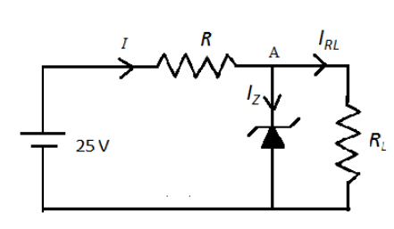
The total current in the circuit is,
I=IRL+IZ
Here, IRL is the current through load resistance and IZ is the current through zener diode.For the maximum current through the load resistor, the current through the zener diode should be the minimum. Therefore,
I=IRL(max)+IZ(min)
We substitute Iz(min)=2mAand I=33.3mA in the above equation.
33.3=IRL(max)+2
⇒IRL(max)=31.3mA
We know that the voltage across the parallel combination remains the same. Therefore, the voltage across the load resistance should be equal to the voltage across the zener diode.
We calculate the load resistance as follows,
RL=IRL(max)VRL
We substitute VRL=10V and IRL(max)=31.3mA in the above equation.
RL=31.3mA10Ω=0.313A10Ω
∴RL=319.5Ω
Therefore, the minimum value of load resistance is 319.5Ω.So, the correct answer is option (D).
Note: We know that KVL states that the sum of voltage drop across each component in the circuit. If there is a drop in the voltage, then the sign of voltage should be negative and if there is addition of voltage then the sign should be positive. In the above circuit, there is drop in the voltage across the resistor and zener diode. The current does not pass through the lower terminal of the zener diode because the zener diode works in reverse bias mode.