Question
Question: Find the equivalent resistance of the network shown in figure between the points \[a\] and \[b\] is:...
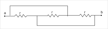
Find the equivalent resistance of the network shown in figure between the points a and b is:
A) 3r
B) 2r
C) r
D) 3r
Solution
In this question, the concept of parallel or series arrangement of the resistance will be used. In this problem first simplify the circuit and draw it in a more simplified way such that we can understand whether the resistances are in series or parallel.
Complete step by step solution:
If we see the given circuit diagram in the question carefully, it can be simplified to a much easier diagram which is represented below in figure number 1. The resistors whose resistance is given asr, are all in parallel. All the 3 resistors are in between points a and b as shown. The concept of parallel connection is that voltage across each branch will be the same but the amount of current flowing in each circuit is different, as it gets divided in each branch.
Now we know in parallel type of connection the resultant resistance of the circuit is written as-
Rnet1=R11+R21+R31+......(1)
Where,Rnet is the total net resistance in the circuit.
R1 is the first resistor given in circuit.
R2 is the second resistor given in circuit.
R3 is the third resistor given in circuit.
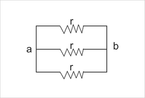
Now here in this question, there are 3 resistors each of resistance r,
⇒R1=R2=R3=r
Hence the net resistance can be calculated as-
Rnet1=r1+r1+r1
After simplification we get,
⇒Rnet1=r3
We get the equivalent resistance as,
∴Rnet=3r
Hence, the net resistance is Rnet=3r.
Thus, the correct option is (D).
Note: The nodal points between which the resistors are present must be very carefully drawn otherwise the marking of the resistors in the simplified diagram can be confusing and can lead to a wrong diagram. Also, without the load-less lines which are drawn parallel to the 1st and 3rd resistor the circuit would have been a series of three resistors only and would have been an easy calculation.