Question
Question: Find the charge on the capacitor after 1 sec of opening the switch at t = ∞? ...
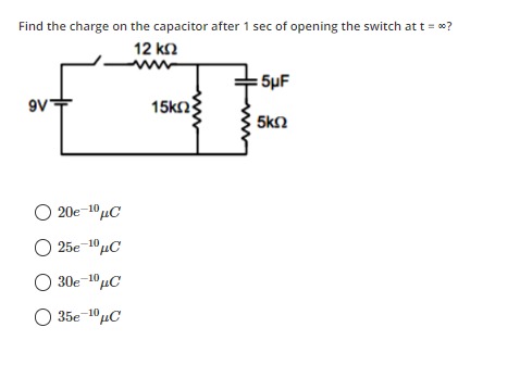
Find the charge on the capacitor after 1 sec of opening the switch at t = ∞?
20e⁻¹⁰ µC
25e⁻¹⁰ µC
30e⁻¹⁰ µC
35e⁻¹⁰ µC
25e⁻¹⁰ µC
Solution
To solve this problem, we need to follow two steps:
- Calculate the initial charge on the capacitor (Q₀) at t = ∞ before opening the switch.
- Calculate the charge on the capacitor after 1 second of opening the switch, considering the discharge process.
Step 1: Calculate the initial charge on the capacitor (Q₀) at t = ∞ (switch closed).
At steady state (t = ∞), a capacitor acts as an open circuit. This means no current flows through the branch containing the capacitor and the 5 kΩ resistor.
The circuit effectively becomes a series circuit with the 9V battery, the 12 kΩ resistor, and the 15 kΩ resistor.
The total resistance in this series circuit is:
Rtotal=12 kΩ+15 kΩ=27 kΩ
The current flowing through this circuit is:
I=RtotalV=27 kΩ9 V=27×1039 A=31×10−3 A=31 mA
The voltage across the 15 kΩ resistor is the voltage across the capacitor (since the capacitor branch is open, no voltage drop across 5 kΩ resistor).
VC(0)=I×15 kΩ=31×10−3 A×15×103Ω=5 V
The initial charge on the capacitor is:
Q0=C×VC(0)=5μF×5 V=25μC
Step 2: Calculate the charge on the capacitor after 1 second of opening the switch.
When the switch is opened, the 9V battery and the 12 kΩ resistor are disconnected from the circuit. The capacitor will now discharge through the remaining resistors.
Let's analyze the discharge circuit. The capacitor (C = 5 μF) is connected between two nodes. Let's call the node connected to the 15 kΩ resistor as Node A and the node connected to the 5 kΩ resistor as Node B. Both Node A and Node B are connected to ground through their respective resistors (15 kΩ and 5 kΩ).
To find the equivalent resistance (Req) for discharge, we need to determine the resistance seen by the capacitor across its terminals.
Let VC be the voltage across the capacitor, VA be the voltage at Node A, and VB be the voltage at Node B.
So, VC=VA−VB.
Let IC be the current flowing out of the positive plate of the capacitor (Node A) and into the negative plate (Node B).
Current through 15 kΩ resistor (R1) is IR1=VA/R1.
Current through 5 kΩ resistor (R2) is IR2=VB/R2.
Applying KCL at Node A: IC+IR1=0⟹IC=−VA/R1. (Assuming IC is current leaving A and entering C, so current leaving A into the circuit).
Applying KCL at Node B: −IC+IR2=0⟹IC=VB/R2.
From these two equations, we have:
−VA/R1=VB/R2⟹VAR2=−VBR1⟹VA=−VBR2R1
Substitute VA into VC=VA−VB:
VC=−VBR2R1−VB=−VB(R2R1+1)=−VBR2R1+R2
Now, solve for VB:
VB=−VCR1+R2R2
Substitute VB back into the expression for IC:
IC=R2VB=R21(−VCR1+R2R2)=−R1+R2VC
For a discharging capacitor, the current is typically defined as IC=−dtdVCC. The general form of discharge equation is I=V/Req.
Here, the current flowing out of the capacitor is Idischarge=−IC=R1+R2VC.
Thus, the equivalent resistance for discharge is Req=R1+R2.
Req=15 kΩ+5 kΩ=20 kΩ
The time constant (τ) for the discharge is:
τ=Req×C=20×103Ω×5×10−6 F=100×10−3 s=0.1 s
The charge on a discharging capacitor at time t is given by:
Q(t)=Q0e−t/τ
We need to find the charge after 1 second (t=1 s):
Q(1 s)=25μC×e−1 s/0.1 s
Q(1 s)=25μC×e−10
So, the charge on the capacitor after 1 second is 25e−10μC.