Solveeit Logo

Question

Question: Find potential of J with respect to G. ![](https://www.vedantu.com/question-sets/7e759047-3508-419...

Find potential of J with respect to G.

& \text{A}\text{. 40}V \\\ & \text{B}\text{. 60}V \\\ & \text{C}\text{. 20}V \\\ & \text{D}\text{. 30}V \\\ \end{aligned}$$
Explanation

Solution

We have given a diagram for which we have to find the potential at node J. We can redraw the diagram in a simple way and then by analysing it we can find the voltage at node J. The node G is ground terminal. We will first find the current flowing through the circuit then by using it we can find the voltage at node J.

Formula used:
V=IRV=IR

Complete answer:
The given circuit can be redrawn as follows

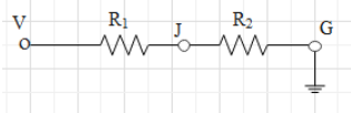
Here V is the main supply whose value is given as 60V. R1 and R2{{R}_{1}}\text{ and }{{R}_{2}}are the resistors connected in series between V and G, the ground terminal, their values are 64Ω and 32Ω64\Omega \text{ and 32}\Omega respectively. Potential at the ground terminal is always zero.
Now, according to Ohm’s law, voltage is given as the product of current and resistance.
V=IRV=IR
We can rewrite the Ohm’s law for the current as
I=VRI=\dfrac{V}{R}
By using the above formula we can find the current flowing through the circuit. Here R will be equivalent to the resistance of R1 and R2{{R}_{1}}\text{ and }{{R}_{2}} and voltage, V is given 60V. As R1 and R2{{R}_{1}}\text{ and }{{R}_{2}}are connected in series therefore above equation will become
I=VR1+R2I=\dfrac{V}{{{R}_{1}}+{{R}_{2}}}
Substituting the values V=60V,R1=64Ω and R2=32ΩV=60V,{{R}_{1}}=64\Omega \text{ and }{{R}_{2}}=\text{32}\Omega we get

& I=\dfrac{60}{64+\text{32}} \\\ & I=\dfrac{60}{96} \\\ & I=0.625A \\\ \end{aligned}$$ As G is ground terminal, so voltage at node J with respect to G can be given as $${{V}_{J}}=I{{R}_{2}}$$ Substituting value of$${{R}_{2}}\text{ and }I$$, we calculated above we get $$\begin{aligned} & {{V}_{J}}=0.625\times 32 \\\ & {{V}_{J}}=20V \\\ \end{aligned}$$ Hence the potential at J with respect to G is 20V. **Correct option is C.** **Note:** The above circuit is similar to Thevenin’s equivalent circuit where V is the input voltage and output is obtained across the J and G terminal. Hence voltage at J will be output voltage and it can be given directly by using Thevenin’s formula. Also note that the equivalent resistance for the resistors connected in series is given as the sum of the resistance of the resistors.