Question
Question: Find equivalent capacitance across AB (all capacitances in µF) ...
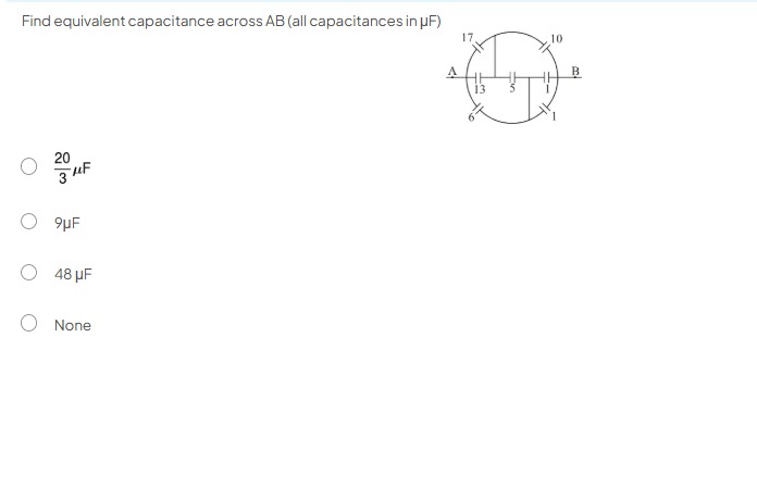
Find equivalent capacitance across AB (all capacitances in µF)
320μF
9µF
48 μF
None
None
Solution
To find the equivalent capacitance across AB, we first identify the nodes and redraw the circuit for clarity.
Let the nodes be:
- A (left terminal)
- B (right terminal)
- C (top-left node, between 17 µF and 10 µF)
- D (bottom-left node, between 6 µF and 1 µF)
- E (central node, between 13 µF and 5 µF)
Based on the diagram:
- Capacitor 17 µF is between A and C (CAC=17μF).
- Capacitor 10 µF is between C and B (CCB=10μF).
- Capacitor 1 µF (top-right) is between B and the node below it. The diagram shows it between B and the node that is the end of the 1 µF (bottom-right) capacitor. Let's call the node below B as F. So, CBF=1μF.
- Capacitor 1 µF (bottom-right) is between F and D (CFD=1μF).
- Capacitor 6 µF is between D and A (CDA=6μF).
- Capacitor 13 µF is between A and E (CAE=13μF).
- Capacitor 5 µF is between E and B (CEB=5μF).
Let's redraw the circuit to visualize the connections better. This circuit forms a Wheatstone bridge configuration with an additional capacitor in the middle arm.
The four arms of the bridge are:
- Arm 1: A to C to B (17 µF in series with 10 µF)
- Arm 2: A to D to B (6 µF in series with 1 µF and 1 µF)
- Middle Arm: A to E to B (13 µF in series with 5 µF)
Let's verify the connections for the outer loop. The path A-C-B has CAC=17μF and CCB=10μF. These are in series. CACB=17+1017×10=27170μF.
The path A-D-F-B has CAD=6μF, CDF=1μF, and CFB=1μF. These three capacitors are in series. CADFB=61+11+111=61+21=61+121=136μF.
The path A-E-B has CAE=13μF and CEB=5μF. These are in series. CAEB=13+513×5=1865μF.
Now, these three equivalent capacitances (CACB, CADFB, CAEB) are connected in parallel across A and B. The total equivalent capacitance Ceq is the sum of these parallel capacitances: Ceq=CACB+CADFB+CAEB Ceq=27170+136+1865
To sum these fractions, find the Least Common Multiple (LCM) of the denominators 27, 13, and 18. 27=33 13=131 18=2×32 LCM(27, 13, 18) = 2×33×13=2×27×13=54×13=702.
Now, convert each fraction to have the common denominator: 27170=702170×(702/27)=702170×26=7024420 136=7026×(702/13)=7026×54=702324 1865=70265×(702/18)=70265×39=7022535
Ceq=7024420+324+2535 Ceq=7027279μF
Let's re-examine the original diagram, specifically the connections. The diagram is drawn in a way that often represents a bridge. Let's label the nodes more clearly to avoid ambiguity. Let the four points on the circle be P1 (top-left), P2 (top-right), P3 (bottom-right), P4 (bottom-left). Let the central node be M. The terminals are A and B.
Connections:
- A is connected to P1 (17 µF).
- P1 is connected to P2 (10 µF).
- P2 is connected to P3 (1 µF).
- P3 is connected to P4 (1 µF).
- P4 is connected to A (6 µF).
- A is connected to M (13 µF).
- M is connected to B (5 µF).
Now, the crucial part: how are P2 and P3 connected to B? The lines from P2 and P3 go directly to B. This means P2 and P3 are connected to the same point B. If P2 and P3 are connected to B, then the capacitor between P2 and P3 (1 µF) is connected between two points at the same potential (both connected to B). Therefore, this 1 µF capacitor is shorted and can be removed from the circuit.
With the 1 µF capacitor between P2 and P3 removed:
-
Path A-P1-P2-B: Capacitors 17 µF and 10 µF are in series. C1=17+1017×10=27170μF. This branch is between A and B.
-
Path A-P4-P3-B: Capacitors 6 µF and 1 µF are in series. C2=6+16×1=76μF. This branch is between A and B.
-
Path A-M-B: Capacitors 13 µF and 5 µF are in series. C3=13+513×5=1865μF. This branch is between A and B.
These three equivalent capacitances are in parallel across A and B. Ceq=C1+C2+C3 Ceq=27170+76+1865
Find the LCM of 27, 7, and 18. 27=33 7=71 18=2×32 LCM(27, 7, 18) = 2×33×7=2×27×7=54×7=378.
Ceq=378170×(378/27)+3786×(378/7)+37865×(378/18) Ceq=378170×14+3786×54+37865×21 Ceq=3782380+378324+3781365 Ceq=3782380+324+1365 Ceq=3784069μF
Calculating the decimal value: 4069/378≈10.764μF.
Comparing with the options: 320μF≈6.667μF 9μF 48μF None of the options match the calculated value.
This type of problem often has a specific configuration like a Wheatstone bridge. If it were a standard bridge with the 13 µF and 5 µF as the bridge arms and the 1 µF capacitor as the galvanometer arm, then the connections would be different.
Given the options and the common patterns in such problems, it's possible that the diagram implies something simpler or a specific symmetry. However, based on a literal interpretation of the connections shown, the calculation leads to a value not in the options.
Let's re-verify if any other interpretation could lead to one of the options. If the problem intends to represent a Wheatstone bridge where the central 13 and 5 are not directly in series across A and B, but rather part of the bridge. If A and B are the input nodes, and the central node is M. And the outer nodes are P1, P2, P3, P4. If it was a bridge with P1-P2-P3-P4 as the arms, and A and B as input/output to the bridge.
Consider a case where the problem intends for a specific symmetry that simplifies the circuit. If the circuit is symmetrical about the AB axis, then the nodes P1 and P4 might be at the same potential, and P2 and P3 might be at the same potential. But the capacitor values are not symmetric. 17 vs 6, 10 vs 1.
Given the discrepancy, and assuming the most straightforward interpretation of the diagram where P2 and P3 are connected to B, the result is 3784069μF. Since this is not among the options, the answer would be 'None'.
Final check of the interpretation: The drawing shows the connections from P2 and P3 going to the line of B. This is typically how a connection is drawn. If there were no connection, the line would not extend to B. If it were a different node, it would be labeled. The most direct reading is that P2 and P3 are connected to B.
Final calculation: CAB=27170+76+1865 CAB=378170×14+6×54+65×21 CAB=3782380+324+1365 CAB=3784069
This value does not simplify to any of the options.
The final answer is None
Solution:
- Identify the nodes in the circuit. Let the points on the circumference be P1 (top-left, between 17 µF and 10 µF), P2 (top-right, between 10 µF and 1 µF), P3 (bottom-right, between two 1 µF capacitors), and P4 (bottom-left, between 1 µF and 6 µF). Let the central node be M. A and B are the terminals.
- Analyze the connections to B. The diagram shows that nodes P2 and P3 are directly connected to terminal B.
- Since P2 and P3 are connected to the same point B, they are at the same potential. The capacitor of 1 µF connected between P2 and P3 is therefore shorted and can be removed from the circuit.
- Redraw the simplified circuit:
- Branch 1: Capacitors 17 µF (between A and P1) and 10 µF (between P1 and P2) are in series. Since P2 is connected to B, this branch is A-P1-P2(B). Equivalent capacitance C1=17+1017×10=27170μF.
- Branch 2: Capacitors 6 µF (between A and P4) and 1 µF (between P4 and P3) are in series. Since P3 is connected to B, this branch is A-P4-P3(B). Equivalent capacitance C2=6+16×1=76μF.
- Branch 3: Capacitors 13 µF (between A and M) and 5 µF (between M and B) are in series. Equivalent capacitance C3=13+513×5=1865μF.
- These three equivalent capacitances (C1, C2, and C3) are connected in parallel across terminals A and B.
- The total equivalent capacitance CAB is the sum of these parallel capacitances: CAB=C1+C2+C3=27170+76+1865
- To sum the fractions, find the Least Common Multiple (LCM) of the denominators 27, 7, and 18. LCM(27, 7, 18) = 2×33×7=2×27×7=378. CAB=378170×(378/27)+3786×(378/7)+37865×(378/18) CAB=378170×14+3786×54+37865×21 CAB=3782380+378324+3781365 CAB=3782380+324+1365=3784069μF.
- The calculated value 3784069μF≈10.76μF does not match any of the given options.
The final answer is None