Question
Question: Figure shows a circuit containing three resistor $X_1, X_2\&X_3$ having resistance $R$ each, an indu...
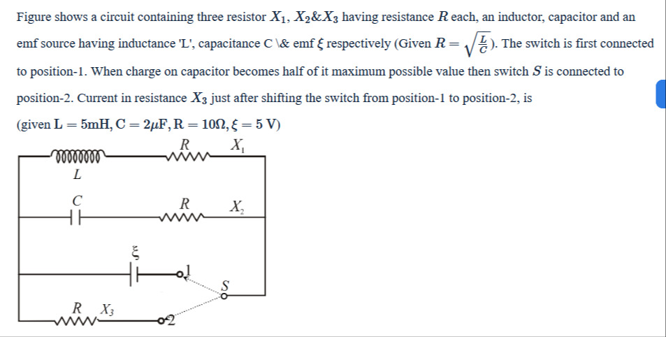
Figure shows a circuit containing three resistor X1,X2&X3 having resistance R each, an inductor, capacitor and an emf source having inductance 'L', capacitance C & emf ξ respectively (Given R=CL). The switch is first connected to position-1. When charge on capacitor becomes half of it maximum possible value then switch S is connected to position-2. Current in resistance X3 just after shifting the switch from position-1 to position-2, is (given L = 5mH, C = 2µF, R = 10Ω, ξ = 5 V)
Answer
0.25
Explanation
Solution
The final answer is 0.25.