Question
Question: In steady state, the capacitor acts as an open circuit. Let the potential at the bottom wire be 0. C...
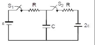
In steady state, the capacitor acts as an open circuit. Let the potential at the bottom wire be 0. Consider the left branch: The battery ϵ is in series with switch S1 and resistor R. This combination is connected to a junction point A. In steady state, the current flowing from the battery ϵ towards A is I1. The potential at A due to this branch is VA=ϵ−I1R. Consider the right branch: Switch S2 is in series with resistor R, and this combination is connected to the positive terminal of battery 2ϵ. The negative terminal of 2ϵ is connected to the bottom wire. This entire branch is also connected to the junction point A. In steady state, the current flowing from the battery 2ϵ towards A is I2. The potential at A due to this branch is VA=2ϵ−I2R. The capacitor C is connected between point A and the bottom wire (potential 0). So, the voltage across the capacitor is VC=VA. Since there is no current flowing through the capacitor in steady state, the current entering point A from the left branch must be equal to the current leaving point A towards the right branch (or vice-versa, depending on the direction of current flow). However, the diagram implies that both branches are connected to point A.
The potential at point A is determined by the parallel combination of the two branches connected to it. In steady state, no current flows through the capacitor, so it acts as an open circuit. Applying Kirchhoff's voltage law to the left loop: ϵ−I1R−VC=0. Applying Kirchhoff's voltage law to the right loop: 2ϵ−I2R−VC=0. Since the branches are connected to a common point A, and the capacitor is between A and ground, the voltage VA is the same for both branches. If we assume the current flows from ϵ through R to A, and from A through R to 2ϵ: VA=ϵ−IR and VA=2ϵ+IR. Equating these gives ϵ−IR=2ϵ+IR⟹2IR=−ϵ⟹IR=−ϵ/2. Substituting this back into the first equation: VA=ϵ−(−ϵ/2)=3ϵ/2. Therefore, the voltage across the capacitor is VC=VA=3ϵ/2. The charge on the capacitor is Q=CVC=C(3ϵ/2).
Solution
In steady state, the capacitor acts as an open circuit, meaning no current flows through it. We need to determine the potential at point A, where the two branches connect, to find the voltage across the capacitor.
Let's assume the bottom wire is at 0 potential.
Left Branch Analysis: The left branch consists of a voltage source ϵ in series with a resistor R. Let I1 be the current flowing from the positive terminal of ϵ towards point A. The potential at point A, considering only this branch, can be expressed using Kirchhoff's voltage law: VA=ϵ−I1R
Right Branch Analysis: The right branch consists of a resistor R in series with a voltage source 2ϵ. Let I2 be the current flowing from the positive terminal of 2ϵ towards point A. The potential at point A, considering only this branch, can be expressed using Kirchhoff's voltage law: VA=2ϵ−I2R
Steady State Condition: In steady state, no current flows through the capacitor. This means that the total current entering junction A must equal the total current leaving junction A. Assuming currents I1 and I2 are directed towards A from their respective sources, and no current flows through the capacitor, the net current at A is I1+I2=0. This implies I1=−I2. This means that if current flows from ϵ towards A, then current must flow from 2ϵ away from A, or vice-versa.
A more common interpretation, and one that leads to a solvable problem, is to consider the potential at point A as the result of these two branches connected in parallel to A. Let's assume the current flows from the higher potential source towards the lower potential source, or that the current from each source flows through its respective resistor to point A.
Let's assume the current I flows from the ϵ source, through R, to point A, and then from point A, through the other R, towards the 2ϵ source. Applying KVL to the left loop: ϵ−IR−VA=0⟹VA=ϵ−IR
Applying KVL to the right loop (going from A towards the 2ϵ source): VA−IR−2ϵ=0⟹VA=2ϵ+IR
Equating the two expressions for VA: ϵ−IR=2ϵ+IR ϵ−2ϵ=IR+IR −ϵ=2IR IR=−2ϵ
Now, substitute this value back into the equation for VA: VA=ϵ−IR=ϵ−(−2ϵ)=ϵ+2ϵ=23ϵ
The voltage across the capacitor, VC, is equal to the potential at point A, since the other side of the capacitor is at ground (0V). VC=VA=23ϵ
The charge on the capacitor is given by Q=CVC. Q=C(23ϵ)