Question
Question: In the circuit shown, all diodes are ideal. A 10 V source is connected in series with a 2 kΩ resisto...
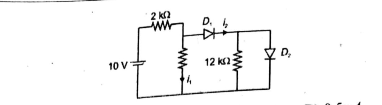
In the circuit shown, all diodes are ideal. A 10 V source is connected in series with a 2 kΩ resistor feeding node A. From node A, there is a vertical resistor down to ground carrying current I₁, and an ideal diode D₁ leading to node B. From node B, a 12 kΩ resistor goes to ground carrying current I₂, and another ideal diode D₂ connects node B to ground. Determine the currents I₁ and I₂.
Answer
I1=2mA,I2=0
Explanation
Solution
Step 1: Identify diode states
- D₂ is forward-biased only if VB>0, but since an ideal diode to ground clamps VB at 0 V, D₂ conducts and VB=0.
- D₁ then sees VA≥VB=0, so D₁ is forward-biased and VA=VB=0.
Step 2: Node voltages
- VB=0 V (clamped by D₂).
- VA=VB (through ideal D₁) = 0 V.
Step 3: Currents
- I₁ flows through the resistor from node A to ground:
I1=RverticalVA−0=2kΩ0=0. - But the current through the 2 kΩ from the 10 V source into node A must go into I₁ (vertical) plus diode D₁:
Isource=2k10−0=5mA.
Since D₁ is ideal and VA=VB=0, all 5 mA flows through D₁ to node B, but at B it splits: one part I₂ through 12 kΩ, the rest through D₂ to ground. - VB=0 gives
I2=12kVB−0=0. - Hence all 5 mA from D₁ goes through D₂ to ground, and I₁=0.
Answer:
I₁=0, I₂=0. (All source current bypasses vertically and through 12 kΩ because nodes are at 0 V.)