Question
Question: The problem provides a circuit diagram showing a resistor $R_S = 6 \Omega$, an ammeter connected in ...
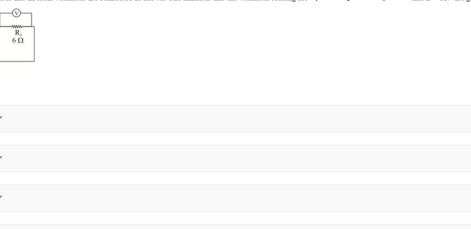
The problem provides a circuit diagram showing a resistor RS=6Ω, an ammeter connected in series with it, and a voltmeter connected in parallel across it. The question text is incomplete, stating "The ammeter and the voltmeter reading for...". Without further information about the power source connected to the circuit (e.g., its voltage or the total current supplied), we cannot determine the specific numerical readings of the ammeter and voltmeter.
However, we can establish the relationship between their readings based on Ohm's Law and the ideal behavior of the meters.
-
Ammeter Connection and Function: An ammeter is always connected in series with the component through which the current is to be measured. An ideal ammeter has zero internal resistance, so it does not affect the current in the circuit. The ammeter in the diagram measures the current (I) flowing through the resistor RS.
-
Voltmeter Connection and Function: A voltmeter is always connected in parallel across the component whose potential difference (voltage) is to be measured. An ideal voltmeter has infinite internal resistance, so it draws no current from the main circuit. The voltmeter in the diagram measures the potential difference (V) across the resistor RS.
-
Ohm's Law: According to Ohm's Law, the voltage across a resistor is directly proportional to the current flowing through it, with the resistance being the constant of proportionality: V=I⋅R
-
Applying Ohm's Law to the Circuit: Given the resistance of the resistor RS=6Ω. Let the ammeter reading be I (in Amperes). Let the voltmeter reading be V (in Volts). Using Ohm's Law for the resistor RS: V=I⋅RS Substituting the value of RS: V=I⋅6
This equation describes the relationship between the ammeter and voltmeter readings. The voltmeter reading will always be 6 times the ammeter reading. Conversely, the ammeter reading will be the voltmeter reading divided by 6.
Conclusion: Without the value of the voltage source or the current supplied to the circuit, specific numerical readings for the ammeter and voltmeter cannot be determined. The ammeter measures the current I flowing through the 6Ω resistor, and the voltmeter measures the voltage V across it. Their readings are related by Ohm's Law as V=6I.
The question is incomplete as it does not provide sufficient information to calculate numerical values for the readings.
The relationship between the ammeter reading (I) and the voltmeter reading (V) is given by Ohm's Law: V=6I. Specific numerical values for I and V cannot be determined due to incomplete question information.
Solution
The circuit shows a resistor (RS=6Ω) with an ammeter in series and a voltmeter in parallel. This is the standard setup to measure current through and voltage across a resistor. By Ohm's Law, V=I⋅RS. Substituting RS=6Ω, we get V=6I. Specific numerical values for V and I cannot be determined without knowing the applied voltage or current from a power source, which is missing from the question.