Question
Question: 10V 1$\Omega$ 2$\Omega$ A B E₁ r=1$\Omega$ G K₁ R...
10V 1Ω
2Ω
A B
E₁ r=1Ω G
K₁
R
Answer
No specific question asked.
Explanation
Solution
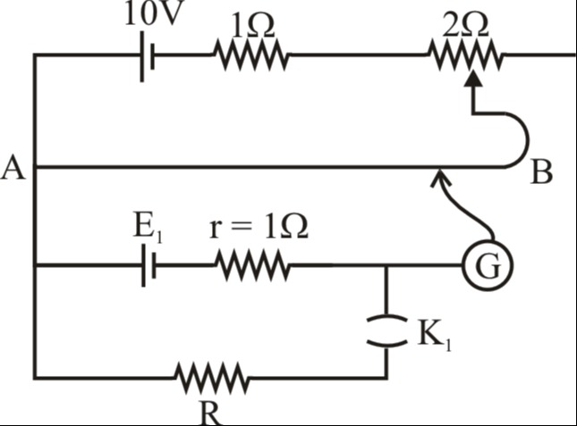
The circuit is a potentiometer.
- Primary circuit: Calculate the potential difference across the potentiometer wire AB. VAB=1Ω+2Ω10V×2Ω=320V.
- Potential gradient: k=LVAB=3L20V/m, where L is the length of the wire AB (not given).
- Secondary circuit (K₁ open): The galvanometer balances the EMF E₁. At balance, E1=kL1, where L1 is the balancing length.
- Secondary circuit (K₁ closed): The resistor R is connected. Assuming R shunts E₁, the terminal voltage Vt across E₁ is balanced. At balance, Vt=kL2, where L2 is the balancing length.
- Internal resistance: r=R(L2L1−1).
Without a specific question or numerical values for lengths/resistance R, a definitive numerical answer cannot be provided. The circuit is used for measuring EMF and internal resistance of a cell.
Answer: No specific question was asked in the prompt. The provided image is a potentiometer circuit typically used for measuring the EMF of a cell and its internal resistance.