Question
Question: Explain with a circuit diagram, how to convert a galvanometer into a voltmeter....
Explain with a circuit diagram, how to convert a galvanometer into a voltmeter.
Solution
Recall the basics function of a galvanometer and a voltmeter. Depending on these functions guess how we can convert a galvanometer into a voltmeter and what should be the values of the extra electric components connected in the circuit for the proper working of the converted voltmeter.
Complete answer:
A galvanometer is the device which is useful to detect a very small electric current in the circuit. The voltmeter is the device which is used to measure the potential difference across the two ends of a current carrying conductor. We can convert a galvanometer into a voltmeter by connecting a resistor with a very large known resistance in series with the galvanometer. The circuit diagram for a galvanometer converted into a voltmeter is as follows:
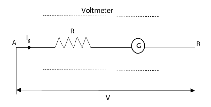
In the above circuit diagram, the galvanometer G is connected in the circuit and is the high resistance resistor R connected in series with the galvanometer between the ends A and B of the current carrying conductor.
The current flowing through the resistor and galvanometer is Ig and the potential difference measured by the voltmeter is V.
Additional information:
The value of the resistance of the resistor connected in the circuit is given by
R=IgV−G
Note: One should keep in mind that if we want to measure the potential difference between the two ends of the conductor accurately, the current flowing between the two ends of the conductor after connecting a measuring device in the circuit should remain the same. This is possible only if the resistance of the resistor connected in series with the galvanometer is infinite.