Question
Question: Explain the working to obtain V-I characteristic curve in forward biasing of P-N junction diodes. Dr...
Explain the working to obtain V-I characteristic curve in forward biasing of P-N junction diodes. Draw a circuit diagram of experimental arrangement.
Solution
You could first explain what exactly is forward biasing. Then you could explain how to obtain the V-I characteristic curve for the same. Also include what happens when a p-n junction diode is forward biased along with a brief description of the circuit arrangement for the same.
Complete answer:
Firstly, let us summarize the formation of p-n junction, and hence understand terms like barrier potential, positive and negative space-charge regions, diffusion, drift, etc.
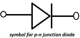
The two electrode device p-n junction is represented by, (direction of the arrow is the conventional direction of current – when in forward bias)
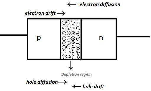
Let us recall that diffusion due to concentration gradient of majority charge carriers (electrons in n-side and holes in p-side) gives rise to diffusion current across junctions and this current further creates a space-charge region which is positive on n-side and negative on p-side called the depletion region. This is followed by the development of an electric field which in turn results in drift current. At equilibrium, (when diffusion current=drift current) p-n junction is formed. The loss and gain of electrons by n and p side respectively produces a potential difference that opposes further flow called the barrier potential.
p-n junction diode in forward bias:
We know that the process in which we apply an external voltage to the circuit is biasing. When biasing is done with the p-side connected to the positive terminal and n-side with the negative terminal, we call it forward biasing.
Due to the high resistance of the depletion region, there is a drop in applied voltage across it. However, the polarity of the applied voltage is opposite to that of built-in potential V0 , hence the width of depletion layer decreases and barrier height is reduced. So, the effective barrier height in forward bias is(V0−V)
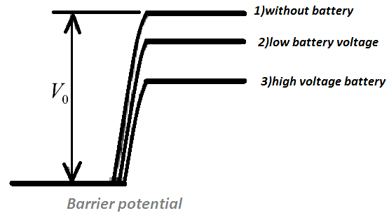
Small applied voltage can only reduce the barrier potential slightly, because, very small number of carriers present in uppermost energy levels will only cross the junction. So we require a significant increase in the applied voltage for more carriers to cross the junction and hence increase the current.
When we apply voltage, minority carrier injection takes place. What happens here is that electrons (minority carriers in p-side) from n-side are crossing the depletion region and reaching p-side. Similarly, holes (minority carriers in n-side) are injected to n-side.
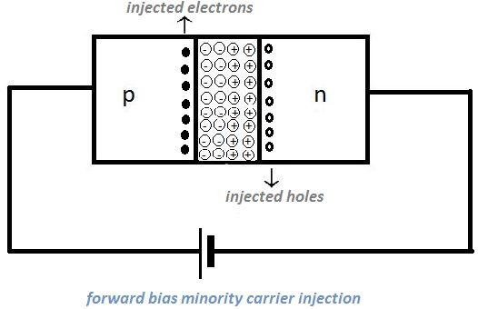
Hence, there is a significant increase in the minority carrier concentration at the junction boundary on each side compared to the edge away from the junction. Here we are again facing a concentration gradient and this further results in diffusion. So, the injected minority carriers diffuse away from the junction end to the other end and give rise to current. So, total diode current =hole diffusion current +conventional current due to electron diffusion, with a magnitude of milli-amperes.
The variation of current with the applied voltage gives the V-I characteristics. The circuit arrangement for studying the same is given by,
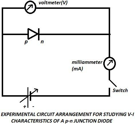
The battery here is connected to the diode via rheostat or a potentiometer since we have to keep changing the applied voltage. Value of current is noted for different values of voltages. The current is expected to be in milli-ampere range and so we use a milli-ammeter. Now, let us look at the V-I characteristics of p-n diodes.
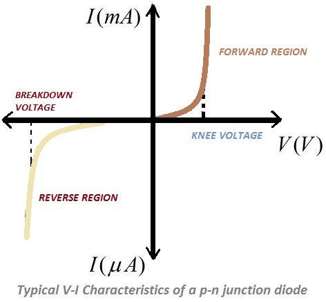
Let us focus on the forward region, here we could observe that the increase in current is quite negligible till a certain voltage. When the voltage hits a particular value we see an exponential increase in current even for very small increase in bias voltage. We call this particular voltage as threshold voltage or cut-in voltage or the knee voltage. Silicon diode is known to have a knee voltage of ~0.7V, and germanium of ~0.2V.
Note:
Make sure that you use a milli-ammeter for measuring the current since the reading is expected to be in that range. Due to high resistance in the depletion region, current first increases negligibly and then faces an exponential increase. So adjust the rheostat accordingly and expect an exponential increase at knee voltage.