Question
Question: Explain the working of a common base transistor amplifier with the help of a circuit diagram. The lo...
Explain the working of a common base transistor amplifier with the help of a circuit diagram. The load resistance of the output circuit is 600kΩ and the resistance of the input circuit is 150pΩ in a common base amplifier. If the current amplification is0.09, then calculate the voltage amplification.
Solution
A common base amplifier is a bipolar junction transistor (BJT) which can amplify the input voltage. The term bipolar refers to the semiconductor used, which is either NPN or PNP, depending on the doping of the material.
Formula used:
V=RiRl×β
Complete answer:
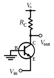
We know that a bipolar junction transistor has three terminals namely, the collector, the emitter and the base. When one of the terminals is grounded, the other two terminals are either forward biased or reversed biased depending on the function of the transistor.
The current gain is a dimensionless number, which is the ratio of the output current to the input current, and is denoted by β. Similarly, the voltage gain is also a dimensionless number, which is the ratio of output voltage to input voltage. Also , the current gain given as β=IbIc, where Ic is in the collector current and Ib is the base current in the circuit.
The bipolar junction transistors have varied uses, like they can be used as a switch or in the amplification of the signals, they are also used in temperature sensors.
Let us consider a common base bipolar junction transistor, where the emitter is grounded.
Given that the current gain β=0.09 , the input resistance is 150pΩ=150×10−12Ω and the load resistance is Rl=600kΩ=600×103Ω .
Then we know that the voltage gain V is given as V=RiRl×β
Substituting we get, V=600×103150×10−12×0.90=22.5×10⁻¹⁷
Hence the voltage gain in the amplifier is 22.5×10⁻¹⁷.
Note:
CB or the common base amplifier is one of the three bipolar junction transistors, the other two are CE or the common emitter and the CC or the common collector. In the circuit, the emitter , base and the collector are grounded respectively.