Question
Question: Draw typical output characteristics of an n-p-n transistor in CE configuration. Show how these chara...
Draw typical output characteristics of an n-p-n transistor in CE configuration. Show how these characteristics can be used to determine output resistance.
Solution
We define output resistance of transistor as the ratio of change in collector-emitter voltage to the resulting change in collector current at constant base current.
Complete step by step solution:
In CE configuration the curve draws between collector current Ic and collector-emitter voltage VCE at a constant base current Ib is called output characteristic. The characteristic curve for the typical NPN transistor in CE configuration is shown in the figure below.
The output characteristics of the n-p-n transistor are given below
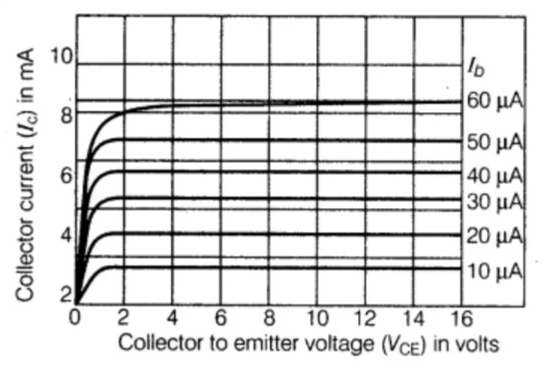
From the output characteristics, we define output resistance of the transistor as the ratio of change in collector-emitter voltage to the resulting change in collector current at constant base current. Thus, output resistance,
r=(ΔICΔVCE) at constant Ib is equal to the reciprocal of the slope of Ic−VCE curve.
The current amplification factor (β)of a transistor in CE configuration is defined as the ratio of change in collector current to the change in base current at a constant collector-emitter voltage when the transistor is in the active state.
So, Amplification factor =(ΔIbΔIc)
Where VCE is constant.
The value of the current amplification is very large.
Additional information:
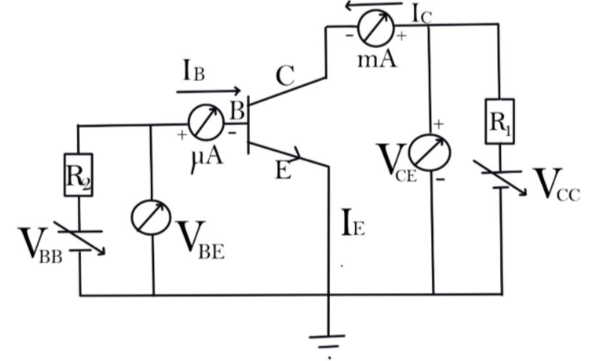
The configuration in which the emitter is connected between the collector and base is known as a common emitter configuration. The input circuit is connected between emitter and base, and the output circuit is taken from the collector and emitter. Thus, the emitter is common to both the input and the output circuit, and hence the name is the common emitter configuration.
In CE configuration, the input current Ib and output current Ic are related by the equation given below:
IE=Ic+Ib
The resistance offered by a p-n junction diode when it is connected to a DC circuit is called static resistance.
Static resistance is also defined as the ratio of DC voltage applied across the diode to the DC current or direct current flowing through the diode.
The dynamic resistance is the resistance offered by the p-n junction diode when AC voltage is applied.
In the AC circuit, charge carriers or electric current do not flow in a single direction. It flows in both forward and reverse directions.
Note:
In the active region, the collector current increases slightly as collector-emitter VCE current increases. The slope of the curve is quite more than the output characteristic of the CB configuration. The output resistance of the common base connection is more than that of the CE connection.