Question
Question: Draw phasor diagram for a series LCR circuit with alternating voltage source, determine the expressi...
Draw phasor diagram for a series LCR circuit with alternating voltage source, determine the expression for the impedance of the circuit.
Solution
Hint: For getting the phasor diagram for the given conditions we will first apply the kvl across the circuit and then from the equations obtained from the kvl we will also get the expressions for the series impedance.
Complete step-by-step answer:
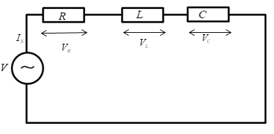
The voltage across each element in the circuit is given by
Let Is=I0sin(ωt)
Applying KVL in the above circuit
V=VR+VL+VC..................(1)
Where
VR is the voltage across the resistor
VL is the voltage across inductor
VC is the voltage across capacitor
Now according to Ohm’s law
V = IR
Now
The voltage across resistor
VR=IsR
The voltage across inductor
VL=IsXL
XL is the reactance of inductor
The voltage across capacitor
Vc=IsXC
XC is the reactance of the capacitor
Substituting these values in the equation (1)
V=IsR+IsXL+IsXC
As we know the current leads the voltage by 90 degree in capacitor and lags by 90 degree in case of inductor.
So, taking the magnitude of above equation and assume XL>XC
V=(IsR)2+(IsXL−IsXC)2 V=IsR2+(XL−XC)2 IsV=R2+(XL−XC)2
Let ISV=Z
Z=R2+(XL−XC)2
Z is known as impedance.
The phasor diagram of the given circuit is shown below.
The resultant vector will be obtained by adding the two vectors VL and VC
Because the two vectors are 180 degree apart as shown in the below figure
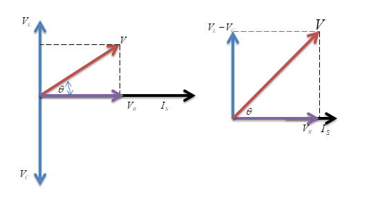
Note – While drawing the phasor diagram, the final reactive voltage must be positive in value therefore take the smallest voltage of the reactive element and subtract it from the largest voltage of the reactive element in the phasor diagram and then take the resultant using the Pythagoras theorem. The current vector is always in phase with the resistance voltage.