Question
Question: Draw a schematic diagram of a circuit consisting of a battery of three cells of \[2V\] each, a \(5\O...
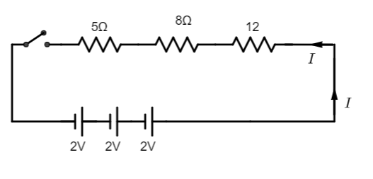
Draw a schematic diagram of a circuit consisting of a battery of three cells of 2V each, a 5Ω resistor, an 8Ω resistor, and a 12Ω resistor, and a plug key, all connected in series.
Solution
We have to remember that a series circuit is defined by the circuit with components arranged in a straight line. We must have to know that hence, the current passing through the components remains the same and the voltage across the circuit is the addition of individual voltage across each component.
Complete step-by-step solution:
We also remember that the resistance in an electric circuit is attached to control the current flow of this circuit and it is measured of the opposition to current flow.
As we know that a battery is a combination of two or more cells that are electrically connected to work together to produce electric energy in a circuit.
We need to remember that a 5Ω resistor, an 8Ω resistor, and a 12Ω resistor are connected in series with a plug key and three cells of voltage 2Veach. Let us assume current I is passing through the circuit. Since this is a series connection the same current will flow through each resistor. We can draw the diagram should be like below:
Note: We have to know that in Series connections have the same current passing through the components. And if the resistances R1,R2,R3 are connected in series, then the equivalent resistance of the series resistances are like R=R1+R2+R3
We also need to remember that in a parallel connection, there is the same potential difference across the components. And if the resistances R1,R2,R3 are connected in parallel, then the equivalent resistance of the parallel resistances are like R1=R11+R21+R31.