Question
Question: Draw a labelled diagram of a step-up transformer. Obtain the ratio of secondary to primary voltage i...
Draw a labelled diagram of a step-up transformer. Obtain the ratio of secondary to primary voltage in terms of the number of turns and the current in the two coils.
Solution
In this question, first draw the transformer circuit then apply the Kirchhoff’s voltage Law that is in a closed-circuit loop, the summation of the voltage across the loop will be zero and also apply the Faraday’s Law to derive the EMF equation.
Complete step by step solution:
First of all, we will draw the circuit diagram of the transformer as,
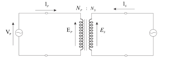
Where, subscripts P and S denote the primary (input) and secondary (output) windings and E denotes the induced voltage across the winding.
Let’s assume that the connecting wires are ideal, that is the voltage drop across the connecting wire is zero.
As we know that according to Kirchhoff’s Voltage law, in a closed-circuit loop, the summation of the voltage across the loop will be zero.
Now, applying Kirchhoff’s Voltage law in both primary and secondary loops as,
According to Faraday’s law, the Emf induced in the circuit is directly proportional to the rate of change of the flux. Now, apply the Faraday’s law for the primary circuit,
EP=−NPdtdϕ
Here, the Emf induced in the primary circuit is Ep, the number of turns in the primary coil is Np, and the rate of change of flux is dtdϕ.
As we obtain from the Kirchhoff’s law that is Vp=Ep, so above equation become,
{E_S} = - {N_S}\dfrac{{d\phi }}{{dt}} \\
{V_S} = - {N_S}\dfrac{{d\phi }}{{dt}} \\
\dfrac{{{V_ P}}}{{{V_S}}} = \dfrac{{ - {N_ P}\dfrac{{d\phi }}{{dt}}}}{{ - {N_S}\dfrac{{d\phi }}{{dt}}}} \\
\dfrac{{{V_P}}}{{{V_S}}} = \dfrac{{{N_P}}}{{{N_S}}} \\
\Rightarrow \dfrac{{{V_P}}}{{{N_P}}} = \dfrac{{{V_S}}}{{{N_S}}} \\
\Rightarrow \dfrac{{{V_S}}}{{{V_P}}} = \dfrac{{{N_S}}}{{{N_P}}} \\
\Rightarrow \dfrac{{{V_{out}}}}{{{V_{in}}}} > 1 \\
\Rightarrow \dfrac{{{N_S}}}{{{N_P}}} > 1 \\
\Rightarrow {N_S} > {N_P} \\