Question
Question: Draw a labelled circuit diagram of a potentiometer to compare emfs of two cells. Write the working f...
Draw a labelled circuit diagram of a potentiometer to compare emfs of two cells. Write the working formula (Derivation not required).
Solution
Hint: A potentiometer consists of a galvanometer, a variable resistance, a battery. In the circuit for the comparison of the emfs of the two cells, the circuit will comprise two cells as well.
Complete step by step solution:
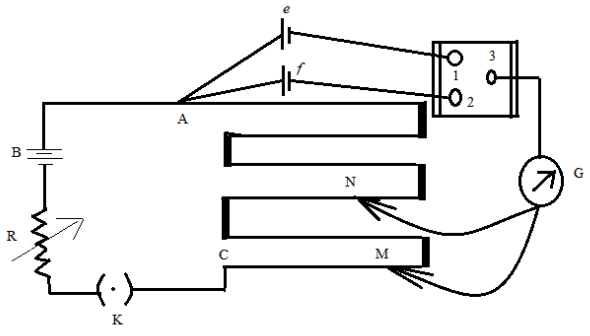
Figure: A potentiometer circuit designed for comparing emfs of two cells.
In the above figure, the wires run from point A to point C. The small vertical portions are metal strips connecting various sections of the wire. B is the battery, R is the variable resistance (the arrow indicates variable resistance) which is also known as the rheostat. e and f are the two cells whose emfs are to be compared. G is the galvanometer and N and M are the two points to which the galvanometer jockey is connected. The points marked 1,2 and 3 form a way key. K is the key of the circuit.
Working formula:
If ε1 is the emf of cell e and ε2is the emf of cell f, then the formula for comparison is given as,
ε2ε1=l2l1
where, l1 and l2 are the distances of point N and M respectively from point A.
Additional Information:
There is also an arrangement of potentiometers for determining the internal resistance of a cell, where we do not need to incorporate the two cells.
Note: Students must note that l1 and l2 are the distances from point A and not from the galvanometer G or point C. And to represent the variable resistance, it is always necessary to give the arrow across the resistance, else it does not represent a variable resistance.