Question
Question: Determine the current through zener diode for the circuit shown in the figure: (Given zener diode br...
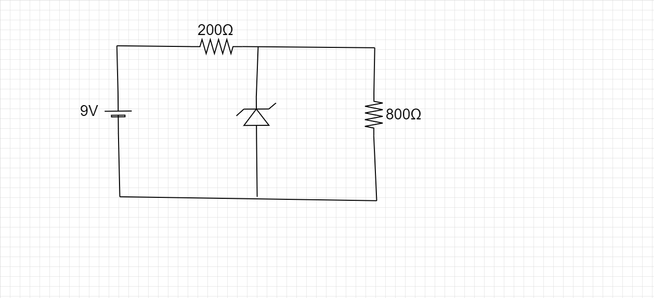
Determine the current through zener diode for the circuit shown in the figure: (Given zener diode breakdown voltage Vz=5.6V
(A) 7mA
(B) 17mA
(C) 10mA
(D) 15mA
Solution
Hint
To solve this numerical, the first step is to apply Kirchhoff's junction law and create a current distribution over the circuit. Then the values of the different currents are calculated and then they are put back into the equation. Also because the load resistance of 800Ω is in parallel with the Zener diode, the voltage around it is regulated. That is, the voltage across it is 5.6V.
Complete step by step answer
Kirchhoff’s current (or junction) law states about conservation of charge in a circuit. So according to the law, the total current entering a junction is always equal to the total current entering a junction. Where junction refers to a common point of intersection for more than two wires. In our circuit, we can define B as a junction.
Let the current which leaves the battery be i1. This i1is the current which enters the junction B.
From here it divides into two smaller currents of i2 and iz. Where i2 is the current which passes through the load resistance of 800Ω. While izis the current which passes through the Zener diode.
So the circuit diagram becomes-
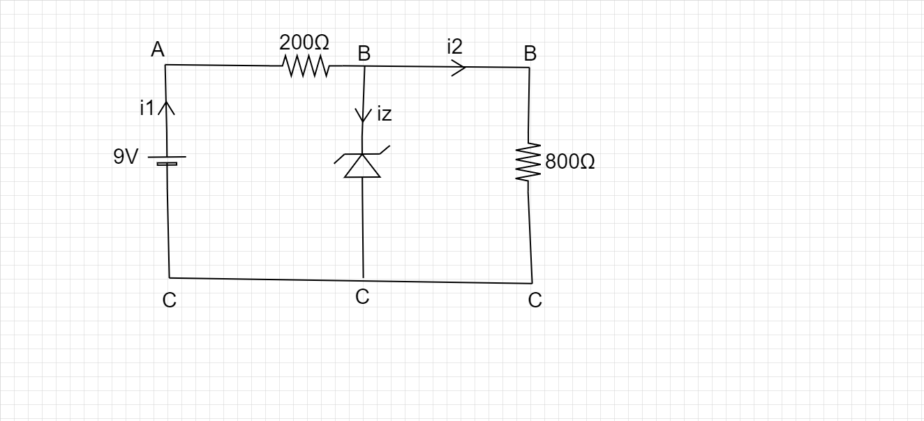
Applying Kirchhoff’s law, we have-
⇒i1=i2+iz
Now, for i2
We know that the Zener diode acts as a voltage regulator and thus voltage across the ⇒800Ω resistance is 5.6V
⇒i=RV (Ohm’s law)
⇒i2=8005.6=7mA
In a series connection voltage divides, therefore the voltage across 200Ω resistances is equal to=
⇒VAB=9−VBC
⇒VAB=9−5.6=3.4V
Current across the 200Ω is
⇒i1=2003.4=17mA
Putting these values in Kirchhoff’s law,
We get,
⇒iz=i1−i2
⇒iz=17−10=10mA
Thus the correct option is (C).
Note
While doing calculations which involve electrical circuits, you can write different points without any load (or other components) under the same name, because they all have the same potential. It has been done in the circuit diagram. This makes the calculations faster and more accurate.