Question
Question: Describe the experiment to compare the E.M.F.’s of two cells by potentiometer under the following he...
Describe the experiment to compare the E.M.F.’s of two cells by potentiometer under the following headings:
A). Circuit diagram
B). Formula
C). Observation table
D). Two precautions
Solution
Hint: The possible gap between a cell's two terminals can be calculated using a voltmeter, but we can calculate the emf value of a given cell using a potentiometer. Where E1 and E2 are two-cell EMFs, l1 and l2 are the lengths for balancing while E1 and E2, respectively, are attached to the circuit and ρ the potential gradient along the wire of the potentiometer.
Complete step-by-step solution -
Part-A
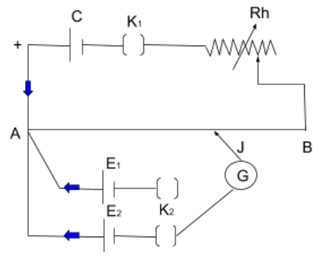
K1 is the Plug key
K2 is the Two-way key
Rh is the Rheostat
J is the Jockey
AB is the Potentiometer wire
G is the Galvanometer
E1,E2 are the Experimental/Sample cells
C is the Lead cell
Part-B
Formula:
Let’s consider E1 to be the E.M.F. of the first cell.
Let the balancing point that was obtained be at a distance of l1. Applying the rule of the principle of potentiometer, we will get-
⇒E1=ρl1
Let the above equation be equation 1.
⇒E1=ρl1 (equation 1)
Let’s consider E2 to be the E.M.F. of the second cell. Let the balancing point be obtained at a distance of l2. Thus-
⇒E2=ρl2
Let this equation be equation 2.
⇒E2=ρl2 (equation 2)
Now, we will divide equation 2 by equation 1, we get-
⇒E2E1=ρl2ρl1=l2l1
Part-C
Observation:
We will observe that the length of the null point for (E2E1=l2l1).
E1=l1cm
E2=l2cm
Part-D
Precautions:
E.M.F. would be greater than the sample cell of the lead cell.
Each positive terminal should always be connected to only one point.
Note: A potentiometer makes an adjustable voltage divider using a three-terminal resistor with a slipping and rotational contact. It functions as a variable resistor or rheostat if only two terminals are used: one end and the wiper. The measurement device known as potentiometer is simply a voltage divider used to calculate strength (voltage); the variable has the same concept and thus the name of the measuring instrument.