Question
Question: Describe briefly with the help of a circuit diagram, how a potentiometer is used to determine the in...
Describe briefly with the help of a circuit diagram, how a potentiometer is used to determine the internal resistance of a cell.
Solution
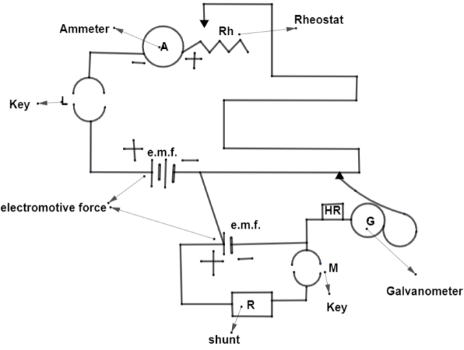
According to the question, as the use of the potentiometer here is to find out internal resistance of a cell, so we will make a circuit with ammeter, galvanometer, rheostat, battery, shunt and keys by which we will measure electromotive force by using resistance against the current flowing in it. There should be two different keys in the circuit.
Formula used:
e.m.f.=I(R+r),V=IR where V is the potential difference and I is the current with resistance R. Here, e.m.f. is electromotive force.
Complete answer:
Potentiometer: It is used for observing pressure created by providing a current through a resistor such that there exists a balance in the potential difference of the circuit.
This pressure which is observed is known to us as an electromotive force which is created between two values of potential difference which is attached to a resistor.
We will consider a long wire with a cross-section area to be as uniform. We will take the wire with a property of high resistance and low temperature coefficient. We will place wires in parallel. As wood will be acting as an insulator so we will form such a circuit on a board made up of wood with an attachment of a meter scale.
Here, we can also see that the joints of the wire are in series joined by thin copper. As the potentiometer is used for the measurement of internal resistance of a cell so, we will form a circuit. The agenda of this circuit is going to be a measure of the potential difference between any two points of the circuit which is having a uniform cross section area and constant current flowing in the circuit. This will make the potential difference directly proportional with the lengthy of the wire of the circuit.
By the relation between electromotive force and potential differences of a cell, we get an equation
e.m.f.=I(R+r)⇒e.m.f.=IR+Ir⇒e.m.f.−Ir=IR
So,
V=IR⇒V=e.m.f.−Ir⇒V+Ir=e.m.f.⇒e.m.f.−V=Ir.
By this equation we mean that the electromotive force is greater than the potential difference with the value of Ir. If we take e.m.f. = IR then we get, V=IR. By ratio of these two equations, we get
IRIr=Ve.m.f.−V⇒Rr=Ve.m.f.−V⇒r=VR(e.m.f.−V)
The cell having e.m.f. E is connected across the resistance by key L. When we open L, we see a deflection IN the galvanometer. This can be shown as e.m.f.=k(length of P). Also, V=k(length of Q). But we obtain a balance point by opening both the switches L and M. By rheostat we can balance length P and Q of the potentiometer. So, we get
r=R(length of Qlength of P-length of Q)
Note:
While making a circuit the following points should be taken into consideration.
(1) The positive side of the ammeter should be attached with a rheostat and the negative side with key L. The circuit should be such that the battery along the line of the key must be in two lines as in the figure named as P and Q respectively leading towards the rheostat.
(2) We will form a small circuit whose battery will be attached with the line of the wire of the first one. The small circuit will consist of a shunt which will be further connected to another key named as M. By including a galvanometer for measurement we will get a small circuit also.
(3) We will say that the circuit is complete if the circuit is attached by the wire of the galvanometer to the line of P. The joints in the circuits are done by using thin copper so that no hindrance will break observations.