Solveeit Logo

Question

Question: Deduce expression for the resultant potential difference, impedance and current in L-R alternating c...

Deduce expression for the resultant potential difference, impedance and current in L-R alternating circuit. Draw a graph to show the phase difference between the current and voltage.

Explanation

Solution

In L-R circuit an inductor and a resistance are connected in series with a voltage source. Due to current in the circuit there is potential drop across the resistor and the inductor.

Complete step by step solution:
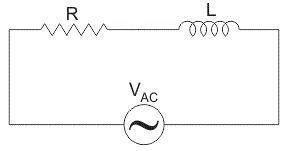
A pure resistance RR and a pure inductive coil of inductance LL as shown connected in series along an alternating current source.


Let V=V=r.m.s. value of the applied voltage,
I=I=r.m.s value of the resultant current in the circuit.
VR=IR{{V}_{R}}=IR is the voltage drop across the resistor which is in phase with the current II,
VL=IXL{{V}_{L}}=I{{X}_{L}} is the voltage drop across the inductor which is ahead of II by 9090{}^\circ .
The applied voltage from the alternating voltage source is the vector sum of the voltage drop across the resistor and the inductor.

& V=\sqrt{V_{R}^{2}+V_{L}^{2}} \\\ & =\sqrt{{{\left( IR \right)}^{2}}+{{\left( I{{X}_{L}} \right)}^{2}}} \\\ & =I\sqrt{{{R}^{2}}+X_{L}^{2}} \end{aligned}$$​​ The quantity $$\sqrt{{{R}^{2}}+X_{L}^{2}}$$​ is known as the impedance of the circuit. Impedance of the circuit is represented as $Z$. As seen from the impedance triangle ABC, ![](https://www.vedantu.com/question-sets/bd71403a-64e4-4d8b-aa06-937d0a65d5f81181388594001033983.png) $\begin{aligned} & {{Z}^{2}}={{R}^{2}}+X_{L}^{2} \\\ & {{\left( \text{Impedance} \right)}^{2}}={{\left( \text{Resistance} \right)}^{2}}+{{\left( \text{Inductive Reactance} \right)}^{2}} \\\ \end{aligned}$ From the given figure it is clear that the applied voltage V leads the current I by an angle ϕ such that ![](https://www.vedantu.com/question-sets/d94f5ced-84d3-4c35-8ba5-9511a40d5d648483859451874384942.png) $\tan \phi =\dfrac{{{V}_{L}}}{{{V}_{R}}}=\dfrac{I{{X}_{L}}}{IR}=\dfrac{{{X}_{L}}}{R}=\dfrac{\omega L}{R}$ $\therefore \phi ={{\tan }^{-1}}\left( \dfrac{\omega L}{R} \right)$ **Note:** \- Across inductor voltage leads the electric current. \- Across the resistor the voltage is in phase with electric current.