Question
Question: Consider the diagram shown. A voltmeter of resistance \(150\Omega \) is connected across A and B. ...
Consider the diagram shown.
A voltmeter of resistance 150Ω is connected across A and B. the potential drop across B and C measured by voltmeter is
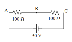
a)29V
b)27V
c)31V
d)30V
Solution
In the above question it is given to us that the voltmeter of resistance 150Ωis connected in parallel with the resistance 100 ohms towards A. First we will determine the equivalent resistance in the circuit. Further using ohm's law we will determine the current in the circuit. Again using ohm's law we will determine the voltage across the BC.
Formula used:
V=IR
RP=R+rrR
Complete step by step answer:
Initially it is given to us that the voltmeter of resistance 150Ωis connected across AB. If there are two resistors i.e. r and R connected in parallel, the equivalent resistance RP in parallel is given by,
RP=R+rrR
Hence using this equation the net resistance across AB is equal to,
RP=R+rrRRP=150+100150×100=25150×10RP=60Ω
Further since resistance in series gets added up, the resistance G between A and C is equal to 160 ohms.
Further using ohm's law i.e. V=IR (where V is the potential difference between the effective resistance R and I is the current in the circuit) the current in the circuit is equal to,
V=IR⇒50V=I160Ω∴I=165=0.31A
Hence again using ohm's law, the voltage measure by the voltmeter between points B and C is equal to,
V=IRVBC=0.31×100=31V
So, the correct answer is “Option C”.
Note:
There are some of the key points that have to be remembered while solving any circuit. The current in series across the resistors remains the same whereas the current in parallel gets distributed across different branches. Similarly the voltage in parallel across the resistors remains the same, whereas the voltage in series circuit gets added up. Considering these points in mind we can solve the basic circuit diagrams easily.