Question
Question: Consider the circuit shown with key opened. Capacitor-1 (3µF) is charged to potential difference of ...
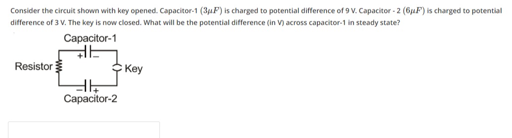
Consider the circuit shown with key opened. Capacitor-1 (3µF) is charged to potential difference of 9 V. Capacitor - 2 (6µF) is charged to potential difference of 3 V. The key is now closed. What will be the potential difference (in V) across capacitor-1 in steady state?
5
Solution
To determine the potential difference across capacitor-1 in steady state, we need to analyze the initial charges on the capacitors and how they redistribute when the key is closed.
1. Initial Charges:
-
Capacitor-1 (C1):
- Capacitance, C1=3μF
- Initial potential difference, V1=9V
- Initial charge on Capacitor-1, Q1=C1V1=(3μF)×(9V)=27μC.
- According to the diagram, the top plate of C1 has a positive charge (+27μC) and the bottom plate has a negative charge (−27μC).
-
Capacitor-2 (C2):
- Capacitance, C2=6μF
- Initial potential difference, V2=3V
- Initial charge on Capacitor-2, Q2=C2V2=(6μF)×(3V)=18μC.
- According to the diagram, the bottom plate of C2 has a positive charge (+18μC) and the top plate has a negative charge (−18μC).
2. Circuit Configuration when Key is Closed: When the key is closed, observe the connections:
- The top plate of Capacitor-1 (initially positive) is connected to the bottom plate of Capacitor-2 (initially positive) via the key. Let's call this common node A.
- The bottom plate of Capacitor-1 (initially negative) is connected to the top plate of Capacitor-2 (initially negative) via the resistor. Let's call this common node B.
In steady state, for a DC circuit with capacitors, there is no current flow through the resistor. Therefore, the potential difference across the resistor is zero. This means that node B (bottom plate of C1 and top plate of C2) will be at a single equipotential. Similarly, node A (top plate of C1 and bottom plate of C2) will be at a single equipotential.
Since the top plate of C1 and the bottom plate of C2 are connected to node A, and the bottom plate of C1 and the top plate of C2 are connected to node B, both capacitors will have the same potential difference across them in steady state, Vf=VA−VB. This configuration effectively puts the capacitors in parallel, with their similarly charged plates connected together.
3. Conservation of Charge: The total charge on the isolated system of plates connected to node A must be conserved.
- Initial charge on node A = (Initial charge on top plate of C1) + (Initial charge on bottom plate of C2)
- QA,initial=(+27μC)+(+18μC)=+45μC.
Let the final potential difference across both capacitors be Vf.
-
Final charge on top plate of C1 = C1Vf
-
Final charge on bottom plate of C2 = C2Vf
-
Final charge on node A = (Final charge on top plate of C1) + (Final charge on bottom plate of C2)
- QA,final=C1Vf+C2Vf=(C1+C2)Vf.
By conservation of charge, QA,final=QA,initial: (C1+C2)Vf=45μC (3μF+6μF)Vf=45μC (9μF)Vf=45μC Vf=9μF45μC=5V.
Thus, in steady state, the potential difference across capacitor-1 (and capacitor-2) will be 5 V. The resistor does not affect the final steady-state potential difference across the capacitors, only the transient charging/discharging process.