Question
Question: Consider a parallel plate capacitor of capacity \( 10\mu F \) with air filled in the gap between the...
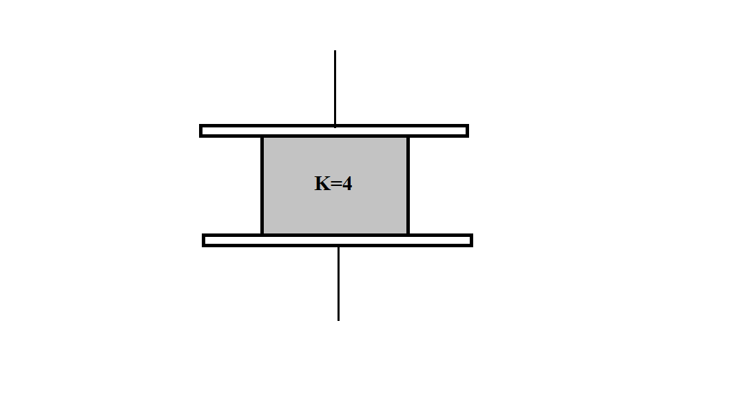
Consider a parallel plate capacitor of capacity 10μF with air filled in the gap between the plates. Now, one-half of the space between the plates is filled with a dielectric constant 4 as shown in the figure. The capacity of capacitor changes to:
A. 25μF
B. 20μF
C. 40μF
D. 5μF
Solution
Hint: Dielectrics in capacitors are used to keep the conducting plates from coming in contact resulting in smaller plate separations and higher capacitance. Dielectrics increase the effective capacitance by reducing the electric field strength. We can find the final capacitance of the combination by considering it as a parallel combination of two capacitors having different values of capacitance.
Formulae used:
C=dεoA
K=εoε
Complete step-by-step answer:
When a dielectric is inserted into a charged capacitor, the dielectric gets polarized by the electric field present between capacitor plates. The electric field from the dielectric will partially cancel the electric field in the capacitor plates. Adding a dielectric into a capacitor allows the capacitor to store more charge for a specified value of voltage.
The dielectric constant K of a material is the ratio of its permittivity ε to the permittivity of vacuum εo . Therefore, K=εoε. The dielectric constant of a material is also known as the relative permittivity of the material. Also, dielectric constant, being a ratio of two similar quantities, is a dimensionless quantity.
For the above set of preparation, let’s take the area of capacitor plates as A and the length of capacitor, distance between two plates, as d . As the dielectric is inserted between the capacitor plates, covering one half of the original space between plates, we can consider this configuration as a parallel combination of two capacitors. The one is with area 2A and having dielectric between its plates and the other one with area 2A and without the dielectric being inserted between its plates.
For capacitors in parallel combination, the resultant capacitance is the sum of individual capacitances
C=C1+C2
Capacitance of half area of original capacitor without dielectric, being air in between the plates, C1=2dεoA
The capacitance of a capacitor having dielectric of dielectric constant K in between its plates is given as CK=KC where C is the capacitance of capacitor with air in between its plates
Capacitance of half area of capacitor having dielectric between its plates, C2=2d4εoA
The effective capacitance of the combination is C=C1+C2
C=2dεoA+2d4εoAC=2d5εoA
Initial capacitance of capacitor is given as 10μF , that is, dεoA=10
C=25×10=25C=25μF
Resultant capacitance of the combination is 25μF
Hence, the correct option is A.
Note: Students should remember the formula for resultant capacitance in series and parallel combination. The formula in case of capacitors is opposite to that of resistors.