Question
Question: Circular loop of a wire and a long straight wire carry current \({{\text{I}}_{\text{0}}}\)and \({{\t...
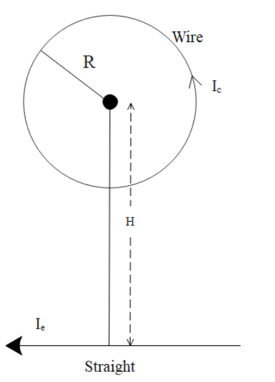
Circular loop of a wire and a long straight wire carry current I0and Ie, respectively as shown in figure. Assuming that these are placed in the same plane, the magnetic fields will be zero at the centre of the loop when the separation H is:
(A). Ic !!π!! IeR
(B). Ie !!π!! IcR
(C). IeR !!π!! Ic
(D). IcRIe !!π!!
Solution
Hint: The solution to this question can be achieved by the use of the formula Ampere’s Circuital Law. Once with the help of this law we find a relationship between the current and the magnetic field, we can get the equations. Equating both the equations, we will get the value of the required variable H.
Complete step by step answer:
We should know that the Ampere’s Circuital Law establishes a relationship between the current and the magnetic field that has been created. This law states that the integral of magnetic field density, denoted by B along an imaginary closed path is equal to the product of current enclosed by the path and permeability of the medium.
Now applying the Ampere’s Circuital Law.
Applying the Ampere's circuital law, we can get the magnetic field of a circular coil due to long straight wire. The equation is as follows:
B1 = 2 !!π!! H !!μ!! 0Ie.
In the above formula,
The value of !!μ!! 0= 4π×10−7H/m
Now, due to the circular coil magnetic field at the centre O is given by B2.
So, B2= 2R !!μ!! 0Ic
Now, from the diagram as we can see that both B1 and B2are in the opposite directions. Therefore, the resultant will be zero, since B1= B2.
So, now equating the formulas we get,
2 !!π!! H !!μ!! 0Ie= 2R !!μ!! 0Ic
So from the above relation we get that the value of H is Ic !!π!! IeR.
Therefore, the correct option is Option A.
Note: We need to consider the direction of current flow to understand the basic nature of the magnetic field flowing through a conductor. Ampere’s Circuital Law and Faraday’s left-hand and right-hand thumb rule helps a lot in determining the direction and force of current in a conductor.