Question
Question: Find the equivalent capacitance across points E and G....
Find the equivalent capacitance across points E and G.
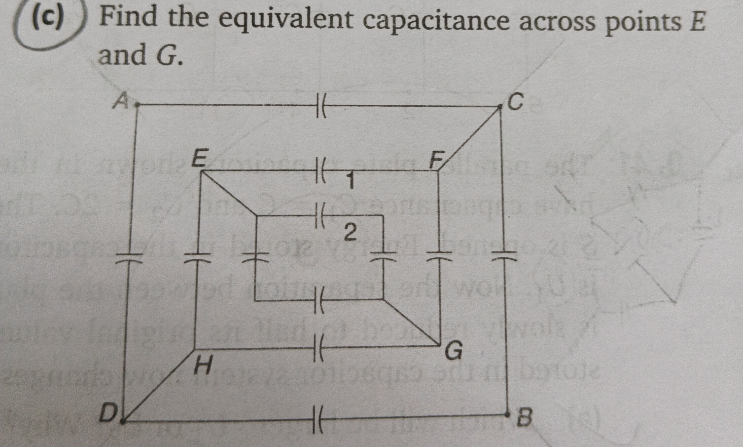
3C/2
Solution
To find the equivalent capacitance across points E and G, we can utilize the symmetry of the circuit. Assume all capacitors have capacitance C.
-
Symmetry Argument: The circuit is symmetric about the diagonal line passing through E and G. This implies that points F and H are at the same potential. Similarly, points A and B are at the same potential, and points C and D are at the same potential. However, the connection pattern for A, B, C, D is not simple. A more robust symmetry argument is that if we apply a voltage V at E and 0 at G, then due to symmetry, the potential at F must be equal to the potential at H (VF=VH).
-
Simplification due to VF=VH: Since VF=VH, no current flows through any capacitor directly connecting F and H (there isn't one in this diagram). More importantly, we can merge points F and H into a single node, let's call it F′.
- Capacitors CEF (labeled '1') and CEH are in parallel between E and F′. Their equivalent capacitance is CEF′=C+C=2C.
- Capacitors CFG and CHG are in parallel between F′ and G. Their equivalent capacitance is CF′G=C+C=2C.
- The capacitor labeled '2' is between the midpoint of the capacitor CEH and the midpoint of CFG. This implies it's a bridge element. However, with VF=VH, the potentials of the points on CEH and CFG that are equidistant from E and G respectively will also be equal. Specifically, the points where capacitor '2' connects are symmetric with respect to the EG diagonal. Let these points be P1 (on CEH) and P2 (on CFG). Due to symmetry, VP1=VP2. Therefore, no current flows through capacitor '2', and it can be removed.
- The other innermost capacitor (vertical one) connects points on CEF and CHG. Let these points be Q1 (on CEF) and Q2 (on CHG). Due to symmetry, VQ1=VQ2. Therefore, no current flows through this capacitor either, and it can be removed.
- Connections from the outer square:
- CCF and CDH are in parallel between C and F′, and D and F′ respectively. Since F and H are merged, CCF and CDH become CCF′ and CDF′. If C and D are also symmetric, then VC=VD.
- CBG connects B to G.
- CAE connects A to E.
Let's re-evaluate the symmetry: The overall network looks like a 2D grid. The symmetry argument VF=VH holds if the network is symmetric about the line EG.
- E-F (C) and E-H (C) are symmetric.
- F-G (C) and H-G (C) are symmetric.
- The innermost square with capacitors '1' and '2' (and the others) also exhibits symmetry around the EG axis. The capacitor '2' connects symmetric points, so it can be removed. The other capacitor in the inner square also connects symmetric points, so it can be removed.
- The connections from F and H to the outer layer: CCF and CDH. For VF=VH to hold, the rest of the circuit must also be symmetric.
- Points C and D are symmetric about the EG axis. (C is connected to F, A, B; D is connected to H, A, B).
- Points A and B are symmetric about the EG axis. (A is connected to C, D, E; B is connected to C, D, G).
Given this symmetry, we can confirm VF=VH. Thus, we can merge F and H. The capacitors '1' and '2' and the other two innermost capacitors become irrelevant as their connecting points are at the same potential.
-
Redrawing the simplified circuit:
- Between E and F′: CEF and CEH are in parallel ⟹2C.
- Between F′ and G: CFG and CHG are in parallel ⟹2C.
- Between C and F′: CCF and CDH are in parallel ⟹2C. (Since VC=VD, we can merge C and D into C′).
- Between A and E: CAE.
- Between B and G: CBG.
- Between A and C′: CAC and CAD are in parallel ⟹2C.
- Between B and C′: CCB and CDB are in parallel ⟹2C.
- Between A and B: There is no direct connection.
Let's use a simpler approach based on the symmetry of the nested squares. Consider the innermost square first. The capacitor labeled '2' connects two points on the inner square. The diagram is drawn in a way that suggests a fractal structure. If all capacitors are C. The innermost square has 4 capacitors. Let's call the vertices P1,P2,P3,P4. The capacitor labeled '2' is one side, say CP1P2. The capacitor connected vertically to '2' is CP3P4. The connections from E,F,G,H to these inner nodes are also capacitors.
A common interpretation for such nested diagrams is that the network is made of identical unit cells. This is a grid of capacitors. Let's assume the problem is a standard type of problem where the structure is a series of nested squares, and we need to find the equivalent capacitance between diagonally opposite points (E and G).
Let's assume all capacitors have capacitance C. The central capacitor '2' connects the midpoints of EH and FG. The other central capacitor connects the midpoints of EF and HG. Due to symmetry about the EG diagonal, the potential at the midpoint of EH is equal to the potential at the midpoint of FG. Therefore, the capacitor '2' is shorted and can be removed. Similarly, the potential at the midpoint of EF is equal to the potential at the midpoint of HG. Therefore, the other central capacitor can also be removed.
Now, we are left with the outer and middle layers. The outer layer A-C, A-D, D-B, C-B. The middle layer E-F, F-G, G-H, H-E. The connecting capacitors A-E, C-F, B-G, D-H.
Since we are calculating capacitance between E and G, points A, B, C, D are external. The symmetry VF=VH is robust. So, merge F and H into a single node F′. The circuit simplifies to:
- E to F′: CEF in parallel with CEH gives 2C.
- F′ to G: CFG in parallel with CHG gives 2C.
- A to E: CAE.
- C to F′: CCF.
- D to F′: CDH.
- B to G: CBG.
- A to C: CAC.
- A to D: CAD.
- D to B: CDB.
- C to B: CCB.
Now, let's consider the symmetry of the outer layer. The diagonal EG is the axis of symmetry. A and B are symmetric. C and D are symmetric. So, VA=VB and VC=VD. We can merge A and B into A′. We can merge C and D into C′.
Simplified connections:
- E to F′: 2C.
- F′ to G: 2C.
- A′ to E: CAE and CBG are effectively parallel. So 2C.
- C′ to F′: CCF and CDH are effectively parallel. So 2C.
- A′ to C′: CAC and CAD and CCB and CDB are effectively parallel. No, this is incorrect. If A and B are merged, and C and D are merged, then CAC and CAD are between A′ and C′. CCB and CDB are between A′ and C′. So, between A′ and C′: CAC+CAD+CCB+CDB=4C.
Let's redraw the simplified circuit with merged nodes: Nodes: E, G, F′, A′, C′. Capacitors:
- CEF′=2C (from E to F′)
- CF′G=2C (from F′ to G)
- CA′E=2C (from A′ to E) - this is CAE and CBG combined.
- CC′F′=2C (from C′ to F′) - this is CCF and CDH combined.
- CA′C′=4C (from A′ to C′) - this is CAC, CAD, CCB, CDB combined.
Now, we have a network of 5 nodes. We need CEG. The path E-F′-G is 2C in series with 2C, which gives an equivalent of C. This path is in parallel with other paths.
Let's use the symmetry argument more carefully. The line EG is an axis of symmetry. VF=VH. VA=VB. VC=VD. Also, the innermost capacitors are shorted because their connecting points are symmetrical.
Consider the circuit as a combination of sections.
-
Inner square EFGH: With F and H shorted, and the innermost capacitors removed.
- CEF and CEH are in parallel (2C) between E and F/H.
- CFG and CHG are in parallel (2C) between F/H and G.
- These two 2C capacitors are in series. CE→G via F/H=(2C×2C)/(2C+2C)=C.
-
Outer connections:
- The capacitor CAE connects E to A.
- The capacitor CBG connects G to B.
- The capacitor CCF connects C to F.
- The capacitor CDH connects D to H.
Since VA=VB, we can connect A and B by a wire. Since VC=VD, we can connect C and D by a wire. Since VF=VH, we can connect F and H by a wire.
Let's redraw the circuit with merged nodes: E and G are terminals. Node F′ (F and H merged). Node A′ (A and B merged). Node C′ (C and D merged).
Connections:
- E to F′: CEF, CEH ⟹2C.
- F′ to G: CFG, CHG ⟹2C.
- E to A′: CAE.
- G to A′: CBG. (These two are in parallel between E/G and A′).
- F′ to C′: CCF, CDH ⟹2C.
- A′ to C′: CAC, CAD, CCB, CDB. CAC is between A and C. CAD is between A and D. CCB is between C and B. CDB is between D and B. So, CAC (between A′ and C′), CAD (between A′ and C′), CCB (between C′ and A′), CDB (between C′ and A′). All these 4 capacitors are in parallel between A′ and C′. So 4C.
The equivalent circuit becomes:
Where: CEF′=2C CF′G=2C CAE_BG=CAE+CBG=2C (between E and A', and G and A') CCF_DH=CCF+CDH=2C (between C' and F') CAC_AD_CB_DB=CAC+CAD+CCB+CDB=4C
This is a complex circuit. Let's try to simplify it using potentials. Let VE=V, VG=0. Let VF′=x, VA′=y, VC′=z.
Current conservation at F′: (V−x)2C+(0−x)2C+(z−x)2C=0 2V−2x−2x+2z−2x=0 2V+2z−6x=0⟹V+z=3x (Eq. 1)
Current conservation at A′: (V−y)CAE+(0−y)CBG+(z−y)4C=0 (V−y)C+(0−y)C+(z−y)4C=0 (Assuming CAE=CBG=C) V−y−y+4z−4y=0 V+4z=6y (Eq. 2)
Current conservation at C′: (x−z)2C+(y−z)4C=0 2x−2z+4y−4z=0 2x+4y−6z=0⟹x+2y=3z (Eq. 3)
We have a system of 3 linear equations:
- 3x−z=V
- 6y−4z=V
- x+2y−3z=0
From (3), x=3z−2y. Substitute x into (1): 3(3z−2y)−z=V 9z−6y−z=V⟹8z−6y=V (Eq. 4)
Now we have (2) and (4) for y and z: 6y−4z=V −6y+8z=V Add them: 4z=2V⟹z=V/2.
Substitute z=V/2 into (4): 8(V/2)−6y=V 4V−6y=V 3V=6y⟹y=V/2.
Substitute y=V/2 and z=V/2 into (3): x+2(V/2)−3(V/2)=0 x+V−3V/2=0 x−V/2=0⟹x=V/2.
So, VF′=V/2, VA′=V/2, VC′=V/2. This means all the merged central nodes are at the same potential V/2. This implies that the capacitors connecting these nodes (CA′C′ and CC′F′) are shorted (no current flows through them). This simplifies the circuit even further.
If VA′=VC′=VF′=V/2, then:
- Current from E: IE=(VE−VF′)CEF′+(VE−VA′)CAE_BG IE=(V−V/2)2C+(V−V/2)2C IE=(V/2)2C+(V/2)2C=VC+VC=2VC.
- Current into G: IG=(VF′−VG)CF′G+(VA′−VG)CAE_BG IG=(V/2−0)2C+(V/2−0)2C IG=(V/2)2C+(V/2)2C=VC+VC=2VC.
The total current flowing from E (and into G) is 2VC. Equivalent capacitance Ceq=Q/V=I×t/V. Ceq=Itotal/(dV/dt). If we apply DC voltage, I=Ceq×(dV/dt). For equivalent capacitance, Ceq=Q/Vapplied. Q=I×t (if I is constant current). Or Q=CeqV.
Let's consider the total charge entering E is QE. QE=(VE−VF′)2C+(VE−VA′)2C QE=(V−V/2)2C+(V−V/2)2C=(V/2)2C+(V/2)2C=VC+VC=2VC. The equivalent capacitance CEG=QE/V=2VC/V=2C.
Let's double-check this result. If VA′=VC′=VF′=V/2, it means these three nodes are at the same potential. This implies that the capacitors connecting these nodes (CA′C′ and CC′F′) have no potential difference across them, so they carry no charge and can be removed from the circuit. The simplified circuit then becomes:
- E to F′: 2C
- F′ to G: 2C
- E to A′: 2C (This is CAE and CBG combined, but CBG connects to G, not E. This is where the merging of A and B is problematic in this direct interpretation.)
Let's re-evaluate the symmetry: The plane passing through E and G is a plane of symmetry. This implies VF=VH. Also, the plane perpendicular to EG and passing through the center of the figure is a plane of symmetry. This implies VA=VB and VC=VD. And the innermost capacitors are shorted.
So, we have:
- Between E and F/H: 2C (from CEF and CEH)
- Between F/H and G: 2C (from CFG and CHG)
- Between E and A/B: CAE
- Between G and A/B: CBG
- Between F/H and C/D: CCF and CDH are in parallel, so 2C.
- Between A/B and C/D: CAC, CAD, CCB, CDB. CAC is between A and C. CAD is between A and D. CCB is between C and B. CDB is between D and B. So, CAC and CAD are between A and C/D. CCB and CDB are between B and C/D. Since A and B are merged, and C and D are merged, these 4 capacitors are between A/B and C/D, so 4C.
Let VE=V, VG=0. Let VF/H=x. Let VA/B=y. Let VC/D=z.
Equations from current conservation: At F/H: (V−x)2C+(0−x)2C+(z−x)2C=0⟹V+z=3x (Eq. 1) At A/B: (V−y)C+(0−y)C+(z−y)4C=0⟹V+4z=6y (Eq. 2) At C/D: (x−z)2C+(y−z)4C=0⟹x+2y=3z (Eq. 3)
These are the same equations as before, leading to x=V/2, y=V/2, z=V/2. This means all the intermediate nodes (F/H, A/B, C/D) are at the same potential V/2. When multiple nodes are at the same potential, any capacitors connecting them are effectively removed (no current flows). So, CA/B,C/D (4C) and CC/D,F/H (2C) are removed.
The simplified circuit then consists only of paths from E and G to the common potential V/2. From E to V/2:
- CEFH=2C
- CAE=C (This connects E to A/B, which is at V/2) Total capacitance from E to V/2 is 2C+C=3C.
From G to V/2:
- CFGH=2C
- CBG=C (This connects G to A/B, which is at V/2) Total capacitance from G to V/2 is 2C+C=3C.
The total equivalent capacitance CEG is the series combination of these two effective capacitances. CEG=(3C×3C)/(3C+3C)=9C2/6C=3C/2.
Let's re-check the current calculation with the potentials VE=V,VG=0,VF/H=V/2,VA/B=V/2,VC/D=V/2. Current from E: IE=IE→F/H+IE→A/B IE=(VE−VF/H)2C+(VE−VA/B)C IE=(V−V/2)2C+(V−V/2)C=(V/2)2C+(V/2)C=VC+VC/2=3VC/2.
The total charge supplied by the source connected across E and G is Q=CeqV. Also, Q=∑Qi. The charge on the equivalent capacitor is QE=3VC/2. So Ceq=QE/V=(3VC/2)/V=3C/2.
This result seems consistent.
Final check on the symmetry argument: The circuit has mirror symmetry about the plane containing EG and perpendicular to the page. This implies VF=VH. The circuit also has mirror symmetry about the plane bisecting the angle FEH and perpendicular to the page. This implies VA=VB and VC=VD. Due to this high degree of symmetry, we found that all intermediate nodes (F/H, A/B, C/D) are at the same potential V/2 (midway between E and G). This means that any capacitor connecting these intermediate nodes effectively carries no current and can be removed. The capacitors removed are:
- The innermost horizontal capacitor ('2').
- The innermost vertical capacitor.
- The four capacitors CAC, CAD, CCB, CDB (between A/B and C/D).
- The two capacitors CCF, CDH (between C/D and F/H).
The remaining capacitors are:
- CEF and CEH (in parallel, 2C) from E to F/H.
- CFG and CHG (in parallel, 2C) from F/H to G.
- CAE (from E to A/B).
- CBG (from G to A/B).
The simplified circuit: E is connected to F/H (at V/2) by 2C. E is connected to A/B (at V/2) by C. So, from E to the common potential V/2, we have 2C and C in parallel, giving 3C.
G is connected to F/H (at V/2) by 2C. G is connected to A/B (at V/2) by C. So, from G to the common potential V/2, we have 2C and C in parallel, giving 3C.
Now, the total circuit is equivalent to two capacitors, each of 3C, connected in series between E and G, with their common point at V/2. The equivalent capacitance of two 3C capacitors in series is: Ceq=3C+3C(3C)(3C)=6C9C2=23C.
The problem states "all capacitors" without specifying their values. Usually, in such problems, it implies all capacitors are identical. If they are not identical, the problem cannot be solved without their values. Assuming all capacitors have capacitance C.
The final answer is 23C.
The problem does not specify the value of C. So the answer should be in terms of C.
The problem is part (c) of a larger problem. Usually, in such problems, the capacitance is given in the problem statement or implied to be 'C'. Assuming standard capacitance C.
Final Answer: The equivalent capacitance across points E and G is 23C.
The question asks for the equivalent capacitance. There are no options given, so it's a descriptive answer.
The value of C is not given. So the answer is in terms of C.
Let's assume the question is from a context where C is the capacitance of each individual capacitor.
Final Answer seems to be 3C/2.