Question
Question: Between the plates of a parallel plate capacitor a dielectric plate is introduced just to fill the s...
Between the plates of a parallel plate capacitor a dielectric plate is introduced just to fill the space between the plates. The capacitor is charged and later disconnected from the battery. The dielectric plate is slowly drawn out of the capacitor parallel to the plates. The plot of the potential difference across the plates and the length of the dielectric plate drawn out is:
Solution
When a parallel plate capacitor is filled up with a dielectric material, its capacitance will be increased by K times. Where, K is the dielectric constant of the given dielectric material.
The voltage drop across the capacitor is inversely proportional to its capacitance. If capacitance increases voltage drops across the capacitor decreases and vice versa.
Complete step by step solution:
When a parallel plate capacitor is filled with free space, its capacitance C=dε0A.
Where, ε0 is the electric permittivity of free space
A is the surface area of a plate of the capacitor
d is the distance between the two parallel plates of the capacitor.
Let h and b are the height and base of each parallel plate of the capacitor.
When the capacitor is filled with dielectric material having the dielectric constant K, its capacitance will become CK=dKε0A.
Now the capacitor filled with dielectric is charged and then disconnected from the battery. The dielectric material is slowly drawn out of the capacitor parallel to the plates.
We can consider this situation as two capacitors C1 and C2 connected in parallel. Where C1 is filled with dielectric and C2 is filled with free space.
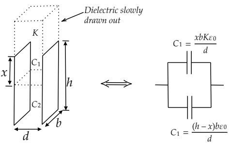
Let x is the height of the parallel plates of the capacitor C1 filled with given dielectric material.
Then the height of the parallel plates of the capacitor C2 is (h−x).
Surface area of a parallel plate of C1 is A1=x⋅b
The capacitance C1=dxbKε0.
In the same way, A2=(h−x)b
And C2=d(h−x)bε0.
The total capacitance of the two capacitors connected in parallel is
CT=C1+C2
Substitute the values of C1 and C2 in the above formula.
⇒CT=dxbKε0+d(h−x)bε0
Further simplifying
⇒CT=bε0d[h+(K−1)x]
We know that the voltage drops (V) across a capacitor is the ratio of charge (q) and capacitance of the capacitor (CT).
Voltage drops V=CTq
Substitute the value of CT in the above formula
⇒V=[h+(K−1)x]bε0qd
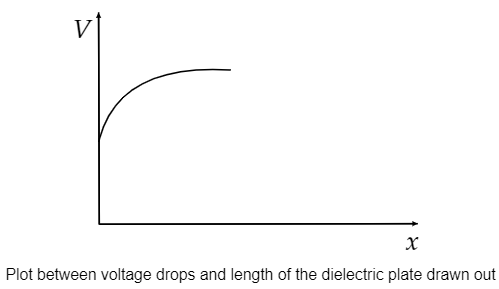
So, when the dielectric material is slowly drawn out from the capacitor, x decreases and the voltage drops. After complete removal of dielectric material from the capacitor, the voltage drops across the capacitor will become constant.
So, the graph between voltage drops and length of the dielectric plate drawn out is as follows.
Note:
It should be noted that the total charge of the capacitor remains constant. When the two capacitors are connected in parallel, its effective capacitance will be the sum of capacitance of each capacitor.
The dielectric constant for a given material is the ratio of permittivity of the material to the permittivity of free space. The dielectric constant is also known as relative permittivity.