Question
Question: As shown in the figure below, A and B are two short steel rods each of cross-sectional area \(5c{{m}...
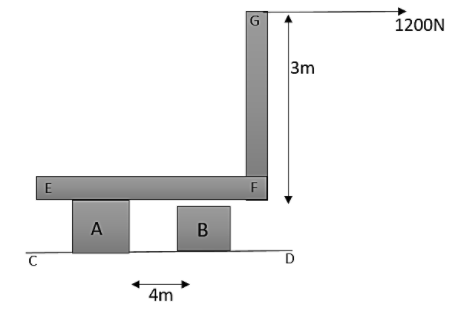
As shown in the figure below, A and B are two short steel rods each of cross-sectional area 5cm2. The lower ends of the rods A and B are welded to a fixed plate CD. The upper end of A is welded to the L−shaped piece EFG, which can slide without friction on the upper end of B. A horizontal pull of 1200N is exerted at G. Note that neglect the weight of EFG. Therefore the longitudinal stress in B is
A. tensile in nature and having a magnitude 180Nm−2
B. tensile in nature and having a magnitude 240Nm−2 180Nm−2
C. compressive in nature and having a magnitude 180Nm−2
D. compressive in nature and having a magnitude 240Nm−2
Solution
First of all draw the diagram of the figure especially the L-shaped piece. Then draw the normal force acting in the diagram. At vertical equilibrium, these normal forces will be equal. Find the torque about E. then find the longitudinal stress acting in B with a help of a free body diagram.
Complete answer:
First of all let us draw the diagram as per the conditions mentioned in the question. Let the normal reaction at A be N1 and at B be N2.
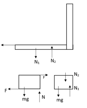
On the L-shaped piece these normal forces will be acting such as N1 in the downward direction and N2 in the upward direction.
In the vertical equilibrium, these normal forces will be equal.
N1=N2
The torque acting about E,
N2×4=1200×3
From this, we will get that,
N2=900
From the free body diagram,
The longitudinal stress acting over B can be written as,
S=5N2=5900=180Ncm−2
This will be compressive in nature also.
Therefore the correct answer for this question is option C.
Note:
The direction of the longitudinal stress acting over a steel rod will be parallel to the longitudinal axis of its centre line axis. This means that it is the stress acting in the direction of the rod’s length. Therefore it is also known as axial stress.