Question
Question: An N-P-N transistor in a common emitter mode is used as a simple voltage amplifier with a collector ...
An N-P-N transistor in a common emitter mode is used as a simple voltage amplifier with a collector current of 4mA. The terminal of a 8V battery is connected to the collector through a load resistance RL, and to the base through a resistance RB. The collector emitter voltage VCE=4V, base-emitter voltage VBE=0.6V and base current amplification factor βdc=100. Calculate the values of RL and RB.
Solution
Apply Kirchhoff’s voltage law to calculate the resistances in the given circuit. It states that the algebraic sum of all electromotive forces and voltage drops across all the resistors is zero for a given closed loop circuit.
The base current amplification factor in common emitter mode is the ratio of collector current and base current. i.e., βdc=IBIC.
Complete step by step answer:
Draw the circuit containing a common-emitter mode N-P-N transistor which is used as a voltage amplifier.
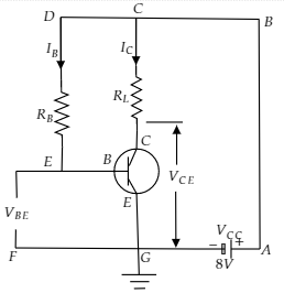
It is given that the potential difference of the battery VCC=8V
The collector emitter voltage VCE=4V
The collector current IC=4mA
Base-emitter voltage VBE=0.6V
Base current amplification factor βdc=100
Apply the KVL to the loop ABCGA, we got
ICRL+VCE=VCC
⇒RL=ICVCC−VCE
Substituting all the required values in the above equation
⇒RL=4×10⁻³A8V−4V
Further calculate.
⇒RL=103Ω
Or RL=1KΩ
Now we know that βdc=IBIC
IB=βdcIC
Substitute the value of IC and βdc in the above formula of IB.
IB=1004×10−3A
Or IB=4×10⁻⁵A
Apply the kVL to the loop CDEFGC, we got
IBRB+VBE=VCC
Simplify above equation for RB.
⇒RB=IBVCC−VBE
Substitute all the required values in the above equation for RB.
⇒RB=4×10⁻⁵A8V−0.6V
⇒RB=1.85×10⁵Ω
Or RB=185kΩ
The values of RL and RB are 1kΩ and 185kΩ respectively.
Note: It should be noted that the emitter-base junction is forward biased and collector-base is reversed biased. The emitter current is equal to the sum of collector current and base current.