Question
Question: An L-C-R series circuit with a resistance of \[100\Omega \] is connected to 200V (AC source) and ang...
An L-C-R series circuit with a resistance of 100Ω is connected to 200V (AC source) and angular frequency 300 rad/s. When only the capacitor is removed, then the current lags behind the voltage by 60∘. When only the inductor is removed the current leads the voltage by 60∘. The average power dissipated in the original L-C-R circuit is:
(a) 50 W
(b) 100 W
(c) 200 W
(d) 400 W
Solution
An L-C-R circuit can be expressed as (in simple words) a circuit having an inductor, resistance and capacitor. We use the phasor diagram to get the relation between the inductance and reactance from which the resonance condition can be proved. Then we will use the condition of resonance to get the value of current. Power dissipation is a product of current, voltage and cosine of the angle between them. Then we will put the values and get the value of power dissipation.
Formulas used:
Power Dissipated=Current × Voltage × cosϕ
Complete step by step answer:
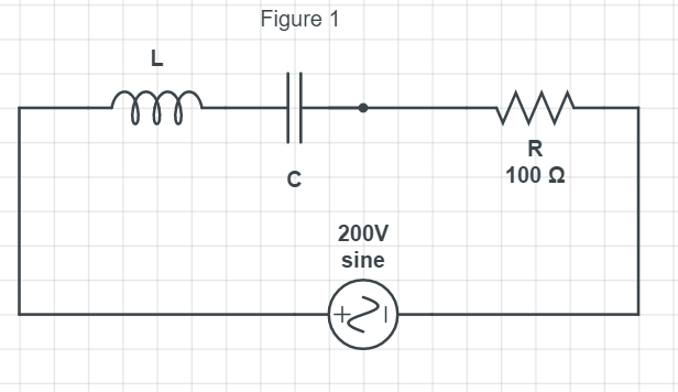
We have been provided with an L-C-R series circuit having a resistance of 100Ω which is connected to an AC source of 200 V. The angular frequency is given as,
ω=300rad/s
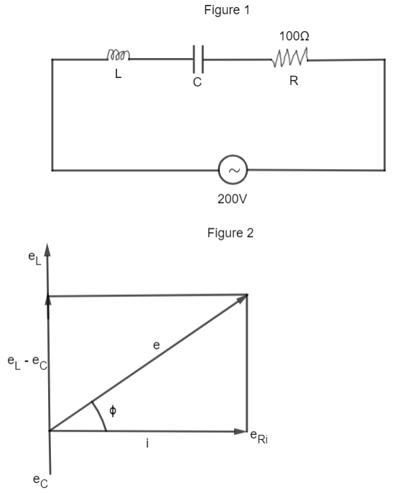
From the phasor diagram shown in figure (1), the current lags voltage by an angle ϕ which is given by
tanϕ=eReL−eC
We know that e = iz, so we get,
tanϕ=RXL−XC.....(i)
Now, we have given that, when the capacitance is removed, the current lags behind the voltage by 60∘, i.e, XC=0.
So, equation (i) can be written as,
tanϕ=RXL=tan60∘
⇒tan60∘=RXL
⇒XL=3R......(ii)
This is the second case when the inductance is removed the current leads the voltage by 60∘, i.e. XL=0.
Therefore, the equation (i) can be written as
tanϕ=RXC
⇒tan60∘=RXC
⇒XC=3R......(iii)
So, from equation (ii) and (iii), we can write as,
XC=XL
We know that the above expression resembles the resonance.
In the AC circuit with an inductor and capacitor, when the frequency of AC is gradually changed at a certain frequency, the impedance becomes maximum or minimum. This condition is called resonance. And we know that if the frequency of the applied voltage is adjusted so that at a particular frequency, XC=XL then Z = R.
Now, let’s calculate the value of power dissipation which is given as,
P=Irms×Vrmscosϕ
where, cosϕ=ZR
To calculate the value of Irms:
The formula of Irms is given by
Irms=ZVrms
(Since Z = R, according to resonance condition)
⇒Irms=100200
⇒Irms=2A
Therefore, the power dissipation is given as
P=2×200×ZR
⇒P=400×100100(∵R=Z)
⇒P=400W
Hence the average power dissipated in the original L-C-R circuit is 400 W.
Therefore, option (d) is the right answer.
Additional Information:
There are two types of resonant circuits: series and parallel. When the alternating current of different frequencies is sent through a series resonant circuit, it offers minimum impedance and high impedance, i.e. the circuit accepts the only current of resonant frequency and rejects the current of other frequencies. Therefore, it is called an acceptor circuit.
Whereas in the parallel resonant circuit, it rejects the current of the resonant frequency but allows the current of the other frequencies to pass through it, hence called the rejector circuit.
Note:
The resistance property of any kind of the circuit which is responsible for the consumption of electric power as heat, while a pure inductor and pure capacitor does not consume any electric power i.e. no heat is produced. Dependence of reactance is on the frequency of the alternating source, while resistance doesn’t depend on the frequency of the source.