Question
Question: An infinite wire is bent in the form of L and carries a current \(I\) as shown in the figure below. ...
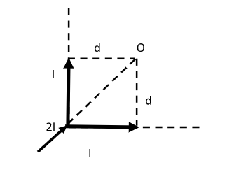
An infinite wire is bent in the form of L and carries a current I as shown in the figure below. Find the magnetic field at point O.
A) Zero
B) 4πμ0×dI
C) 4πμ0×2dI
D) 4πμ0×d2I
Solution
The infinitely long wire bent in the shape of L constitutes two semi-infinite wires. The magnetic field at point O due to the two wires will be opposite in direction at the point of intersection as the current flow has different directions in the two wires.
Formula used:
The magnetic field at a point O for a finite wire carrying a current I is given by, B=4πdμ0I(sinθ1+θ2) where d is the perpendicular distance from the point O to the wire, μ0 is the permeability of free space and θ1, θ2 are the angles formed at point O by line segments joining each end to O.
Complete step by step answer:
Step 1: Sketch a figure representing the infinitely long wire bent in the form of L and list the parameters involved.
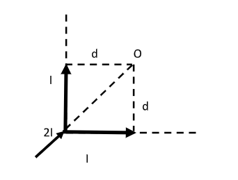
Here, the infinitely long wire is bent in the shape of L. We can now treat this infinitely long wire as two semi-infinite wires. For each wire, one end is finite and the other end is infinitely long.
A current I flows through each wire, 2I represents the current at the junction of the two wires.
A point O is considered such that the perpendicular distance between point O and the wire is d.
The magnetic field at point O is unknown.
Step 2: Find the magnetic field at point O due to the current in the wire placed along the vertical direction.
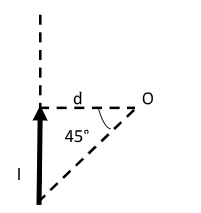
Let Bv be the magnetic field at point O due to the current in the wire placed along the vertical direction.
We have the magnetic field at point O as Bv=4πdμ0I(sinθ1+sinθ2) --------- (1)
Here, d is the perpendicular distance from the point O to the wire, μ0 is the permeability of free space.
Also, θ1 and θ2 are the angles formed at point O by line segments joining the infinite end and finite end of the wire respectively to the point O.
For the infinite end, θ1=90∘ and for the finite end, θ2=45∘ .
Then equation (1) becomes, Bv=4πdμ0I(sin90∘+sin45∘)=4πdμ0I(1+21)
Therefore, the magnetic field at O due to the current in the wire placed along the vertical direction is Bv=4πdμ0I(1+21) -------- (A)
Step 3: Find the magnetic field at point O due to the current in the wire placed along the horizontal direction.
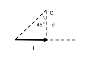
Let Bh be the magnetic field at point O due to the current in the wire placed along the horizontal direction.
We have the magnetic field at point O as Bh=4πdμ0I(sinθ3+sinθ4) --------- (2)
Here, d is the perpendicular distance from the point O to the wire, μ0 is the permeability of free space.
Also, θ3 and θ4 are the angles formed at point O by line segments joining the infinite end and finite end of the wire respectively to O.
For the infinite end, θ3=90∘ and for the finite end, θ4=45∘.
Then equation (2) becomes, Bh=4πdμ0I(sin90∘+sin45∘)=4πdμ0I(1+21)
Therefore, the magnetic field at O due to the current in the wire placed along the horizontal direction is Bh=4πdμ0I(1+21) -------- (B)
Step 4: Find the net magnetic field at point O.
We thus have, the magnetic fields at point O due to the current in the two semi-infinite wires as given by equations (A) and (B) as Bv=4πdμ0I(1+21) and Bh=4πdμ0I(1+21)
When the right-hand thumb rule is used at the point of intersection, the magnetic field lines will have two directions since the current flow along the two wires is different. The point O is essentially an imaginary point that actually exists at the point of intersection.
So, the net magnetic field at the point of intersection is Bnet=Bv−Bh=0.
Therefore, the magnetic field at point O is zero.
Note:
The right-hand thumb rule gives us the direction of the magnetic field at a point when the direction of the current is known. According to the right-hand thumb rule we consider a current-carrying wire in our right hand. Now the thumb points in the direction of the current and all the finger curling around the wire will give the direction of the magnetic field.