Question
Question: An inductor \[\left( {L = \dfrac{1}{{100\pi }}{\rm{H}}} \right)\], a capacitor \[\left( {C = \dfrac{...
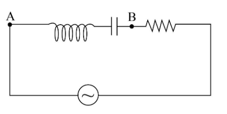
An inductor (L=100π1H), a capacitor (C=500π1F) and a resistance(3Ω) is connected in series with an AC voltage source as shown in the figure. The voltage of the AC source is given as V=10cos(100πt)Volt. What will be the potential difference between A and B?
(A) 8cos(100πt−127∘)Volt
(B) 8cos(100πt−53.13∘)Volt
(C) 8cos(100πt−37∘)Volt
(D) 8cos(100πt+37∘)Volt
Solution
We will write the expression for impedance of a given R-L-C circuit which gives us the relation between capacitive reactance, inductive reactance and resistance of the circuit. We will use the concept of voltage derived from Ohm’s law to write the final expression for the potential difference between A and B.
Complete step by step answer:
Given:
The inductance of the inductor is L=100π1H.
The capacitance of the capacitor is C=500π1F.
The resistance of the resistor is R=3Ω.
The voltage of the AC source is V=10cos(100πt)Volt.
We know that the general form of the AC voltage is V=100cos(ωt)Volt. On comparing the given voltage of AC source with its general expression, we will get the value of frequency as below:
ω=100πHz
Let us write the expression for impedance of the given L-C-R circuit.
Z=(XC−XL)2+R2…...(1)
Here XC is the capacitive reactance and XL is the inductive reactive and R is the resistance of the given R-L-C circuit.
We can write the expression for capacitive reactance as below:
XC=ωC1
On substituting 500π1F for C and 100πHz for ω in the above expression, we get:
We can also write the expression for inductive reactance as below:
XL=ωL
On substituting 100π1H for L and 100πHz for ω in the above expression, we get:
On substituting 5Ω for XC, 1Ω for XL and 3Ω for R in equation (1), we get:
Z=(5Ω−1Ω)2+3Ω2 =5ΩWe can write the expression for phase difference as below:
ϕ=tan−1(RXC−XL)
On substituting 5Ω for XC, 1Ω for XL and 3Ω for R in the above expression, we get:
We can write the expression for the current of the given circuit as the ratio of voltage and impedance of the circuit.
I=ZV
We know that the phase difference is the lag of current with a potential difference so that we can substitute 10cos(100πt−ϕ)Volt for V and 5Ω for Z in the above expression.
Now we will substitute 53.13∘ for ϕ in the above expression.
I=2cos(100πt−53.13∘)A
We can write the impedance between point A and point B as the difference between capacitive and inductive reactance.
R′=XC−XL
On substituting 5Ω for XC and 1Ω for XL in the above expression, we get:
The potential difference between point A and point B is given by:
V′=IR′
On substituting 4Ω for R’ and 2cos(100πt−53.13∘)A for I in the above expression, we get:
Therefore, the potential difference between A and B is 8cos(100πt−53.13∘)Volt, and option (B) is correct.
Note: Do not forget to subtract the phase difference from potential difference while writing the expression for current through the given circuit. The unit of inductive reactance, capacitive reactance is the same as the unit of resistance, so do not confuse with that.