Question
Question: An inductor and a resistor in series are connected to an A.C. supply of variable frequency. As the f...
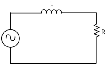
An inductor and a resistor in series are connected to an A.C. supply of variable frequency. As the frequency of the source is increased, the phase angle between current and the potential difference across L will
A. First increase and then decrease
B. First decrease and then increase
C. Go on decreasing
D. Go on increasing
Solution
Here we have to find a relation between the frequency of the applied AC source and the phase angle between the current and the potential difference across L, so it will help to find the variation in phase as frequency is increased. To get this, use the vector method.
Complete step by step answer:
In vector method, the resistance is represented by a vector of magnitude R along the x-axis and the reactance of the inductor is represented by a vector of magnitude XL along the negative y-axis which will be lagging behind the resistance vector by a phase of 2π. The vector sum gives the impedance of the circuit and the phase angle.
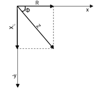
From here, you can find the tangent of the phase angle ϕ
tanϕ=RXL
XL is the reactance of inductor and is given as XL=ωL, where ω is the angular frequency of the applied voltage and L is the inductance of the inductor.
Now, tanϕ=RωL.
If the frequency of the applied source increases, the tangent of the phase angle increases. Implying that the phase angle between the current and the potential difference will also increase.
Hence, as the frequency of the source is increased, the phase angle between current and the potential difference across L will go on increasing.Therefore,option (D) is correct.
Additional information:
In the above case, the current is given as I=(R2+XL2)V0sin(ωt−ϕ), here V0is the peak voltage. The applied voltage is given by V=V0sinωt. From the equations of current and voltage, we conclude that in an LR circuit, the current lags the voltage.
In case of RC circuit, the tangent of the phase angle is given as tanϕ=R−XC, as one can see that the phase angle will come out to be negative. Now, as I=(R2+XL2)V0sin(ωt−ϕ), the phase angle will nullify the negative sign and the overall phase will be positive, meaning the voltage will lag the current.
Note: Always remember the vector representation. The resistance is represented along the x-axis, reactance of inductor along negative y-axis and reactance of capacitor along positive y-axis. This will help you in solving many questions related to alternating current.