Question
Question: An inductor \(20mH\), a capacitor \(50\mu F\) and a resistor \(40\Omega \) are connected in series a...
An inductor 20mH, a capacitor 50μF and a resistor 40Ω are connected in series across a source of emf V=10sin(340t). The power loss in AC circuit is:
A. 0.51WB. 0.67WC. 0.76WD. 0.89W
Solution
Hint: When the components, inductor, capacitor, and resistor are connected in series in a circuit, the average power dissipated can be expressed in terms of the RMS voltage and current. We will find the expression for power dissipation in a series LCR circuit using the equation of impedance in an AC circuit.
Formula used:
P=R2+(ωL−ωC1)2E2R
Complete step by step answer:
An RLC circuit is an electrical circuit which consists of a resistor (R), an inductor (L), and a capacitor (C) connected in series or in parallel.
Series RLC circuit:
In this circuit, the three components are all connected in series with the voltage source.
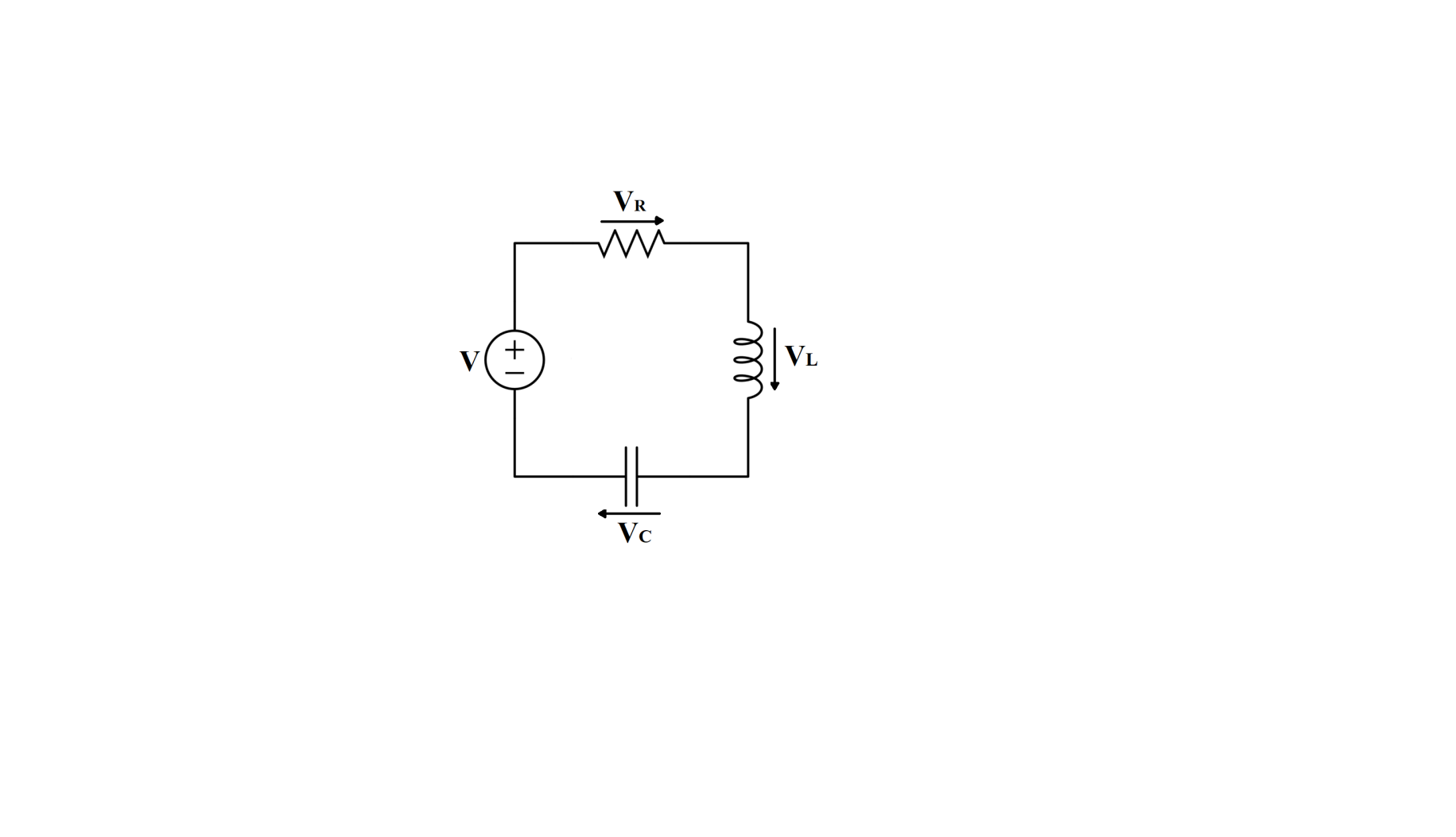
From KVL,
VR+VL+VC=V(t)
Where,
VR is the voltage across R
VL is the voltage across L
VC is the voltage across C
V(t) is the time varying voltage from the source
We are given,
Inductance, L=20mH
Capacitance, C=50μF
Resistance, R=40Ω
The EMF of the electrical circuit is E
The impedance of the series LCR circuit is given as,
Z=R2+(ωL−ωC1)2
The power factor in a series LCR circuit is given as,
cosϕ=∣Z∣R
The power dissipated in the circuit is given as,
P=VrmsIrmscosϕ
We have,
Vrms=E
Irms=∣Z∣E
cosϕ=∣Z∣R
Therefore,
P=E×∣Z∣E×∣Z∣R
Put Z=R2+(ωL−ωC1)2
P=R2+(ωL−ωC1)2E2R
Thus,
Power dissipated in the series LCR circuit is given as,
P=R2+(ωL−ωC1)2E2R
We are given that an inductor 20mH, a capacitor 50μF and a resistor 40Ω are connected in series across a source of EMF V=10sin(340t).
EMF of the circuit, V=10sin(340t)
Impedance of the circuit is given as,
Z=R2+(XL−XC)2
XL=ωLXC=ωC1
Given values,
L=20mH
C=50μF
R=40Ω
ω=340
We get,
Z=(40)2+(340×20×10−3−340×50×10−61)2⇒Z=1600+2704⇒Z=4304⇒Z=65.60Ω
Power loss in AC circuit is given as,