Question
Question: An alternating voltage source of peak voltage $V_0$ is connected across a series combination of an i...
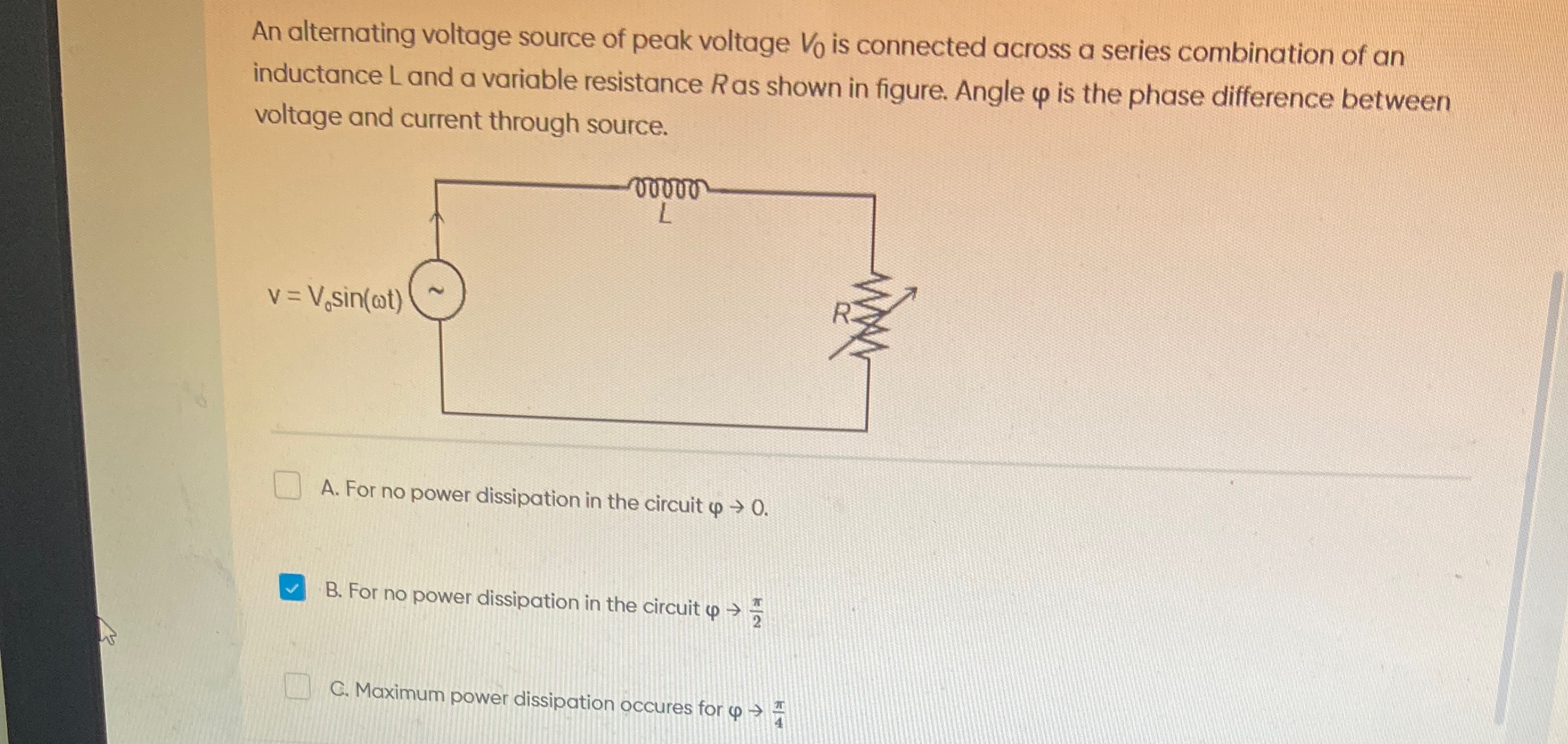
An alternating voltage source of peak voltage V0 is connected across a series combination of an inductance L and a variable resistance R as shown in figure. Angle φ is the phase difference between voltage and current through source.
For no power dissipation in the circuit φ→0.
For no power dissipation in the circuit φ→2π
Maximum power dissipation occures for φ→4π
Options B and C are correct.
Solution
The circuit described is a series L-R (Inductor-Resistor) circuit connected to an alternating voltage source. The instantaneous voltage is v=V0sin(ωt). The phase difference between the voltage and current is denoted by φ.
The impedance of the L-R series circuit is Z=R2+XL2, where XL=ωL is the inductive reactance. The phase difference φ between the voltage and current is given by:
tanφ=RXL
The average power dissipated in an AC circuit is given by:
Pavg=VrmsIrmscosφ
where Vrms=2V0 is the RMS voltage and Irms=ZVrms is the RMS current. The term cosφ is known as the power factor. From the impedance triangle, cosφ=ZR=R2+XL2R.
Substituting these into the power equation:
Pavg=Vrms(ZVrms)(ZR)=Z2Vrms2R=R2+XL2Vrms2R
A. For no power dissipation in the circuit φ→0.
If φ→0, then cosφ→cos0=1. In this case, Pavg=VrmsIrms(1)=VrmsIrms. This corresponds to a purely resistive circuit (XL=0 or R→∞). If XL=0, then Pavg=Vrms2/R, which is generally non-zero. If R→∞, then Irms→0, so Pavg→0. However, φ=0 generally means maximum power factor, not no power dissipation. Therefore, statement A is incorrect.
B. For no power dissipation in the circuit φ→2π.
For no power dissipation, Pavg=0. Since Vrms and Irms are generally non-zero, this requires cosφ=0. This implies φ=2π (or 90∘). In an L-R series circuit, tanφ=RXL. If φ=2π, then tanφ→∞, which means R→0. When R=0, the circuit is purely inductive. In a purely inductive circuit, the current lags the voltage by π/2, and the average power dissipated is indeed zero (inductors store and release energy, but do not dissipate it as heat). Thus, statement B is correct.
C. Maximum power dissipation occurs for φ→4π.
To find the condition for maximum power dissipation, we need to maximize Pavg=R2+XL2Vrms2R with respect to the variable resistance R.
We differentiate Pavg with respect to R and set the derivative to zero:
dRdPavg=Vrms2dRd(R2+XL2R)
Using the quotient rule:
dRdPavg=Vrms2(R2+XL2)2(R2+XL2)(1)−R(2R)=Vrms2(R2+XL2)2R2+XL2−2R2=Vrms2(R2+XL2)2XL2−R2
Setting dRdPavg=0 gives XL2−R2=0, which implies R2=XL2. Since R and XL are positive, the condition for maximum power dissipation is R=XL.
Now, let's find the phase angle φ when R=XL:
tanφ=RXL=XLXL=1
Therefore, φ=tan−1(1)=4π (or 45∘). Thus, maximum power dissipation occurs when φ→4π. Statement C is correct.
Both statements B and C are correct based on the principles of AC circuits.
Explanation of the solution:
- Average Power Formula: The average power dissipated in an AC circuit is Pavg=VrmsIrmscosφ, where φ is the phase difference between voltage and current.
- No Power Dissipation: For Pavg=0, we must have cosφ=0, which implies φ=2π. This occurs when the circuit is purely reactive (e.g., R=0 for an L-R circuit).
- Maximum Power Dissipation: For an L-R series circuit with variable resistance R, the average power is Pavg=R2+XL2Vrms2R. Differentiating Pavg with respect to R and setting to zero yields the condition for maximum power: R=XL.
- Phase Angle for Maximum Power: When R=XL, the phase angle φ is given by tanφ=RXL=XLXL=1, which means φ=4π.