Question
Question: An AC source is connected in parallel with an \[{\text{L - C - R}}\;\] circuit as shown. Let \[{I_S}...
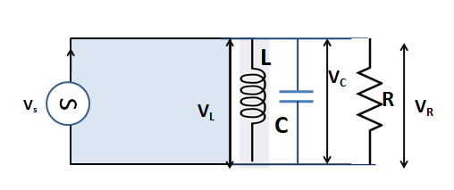
An AC source is connected in parallel with an L - C - R circuit as shown. Let IS,IL,IC and IR denote the currents through and VS ,VL ,VC, VR voltages across the corresponding components. Then:
(A)IS= IL− IC− IR
(B)VS= VL+ VC+ VR
(C)(IL, IC, IR)< IS
(D)IL,ICmay be greater than IS
Solution
The parallel L - C - R circuit is the exact opposite of the series L - C - R circuit. The total current from the supply will not be the algebraic sum of the currents of the branch but the vector sum of those currents. Find the relation between the total current with the branch currents from the phasor diagram and put the condition of resonance, you will find the answer.
Formula used:
For a parallel L - C - R circuit, Is2=IR2+(IL−IC)2
Here, Is is the total current of the circuit, IL is the current across voltage VL , IC is the current across voltage VC, IR is the current across the voltage VR.
At resonance, Is=IR
Complete step by step answer:
The given circuit shows that an AC source is connected to a parallel L - C - R circuit.

If we want to look at the current flow, we may draw the circuit like this by including the current flowing directions,
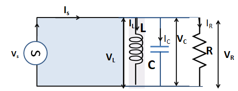
So, the currents IL,IC and IR are flowing through the inductor, capacitor, and resistor respectively. The voltages across the inductor, capacitor, and resistor are VL ,VC and VR respectively.
From the phasor diagram of a parallel L - C - R circuit shown below, we can see that the vector components of the currents produce a right-angle triangle.
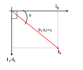
From this diagram, we can write, Is2=IR2+(IL−IC)2
Now, At resonance, Is=IR
So, Is2=IR2+(IL−IC)2
⇒Is2=Is2+(IL−IC)2
⇒(IL−IC)2=0
⇒IL=IC
From these relations, we can say that the currents through the inductor and the capacitor both might be greater than the current through the supply.
Hence the correct answer is in option (D)⇒IL,ICmay be greater than IS.
Note: The analysis of a parallel L - C - R circuit is difficult than a series L - C - R circuit. So to find the relations between the current components we have taken only pure components to keep things simple. Here the current flowing through each brunch will not be the same to each other and also to the source current Is that is across the supply voltage Vs. The phasor diagram for a parallel L - C - R circuit is produced by the together combination of three individual phasors for each of the components and adding by the vector method.