Question
Question: A uniform rod of mass \( m \) and length \( l \) can rotate in a vertical plane about a smooth horiz...
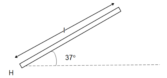
A uniform rod of mass m and length l can rotate in a vertical plane about a smooth horizontal axis hinged at point H. Find angular acceleration α of the rod just after it is released from the initial position making an angle of 37∘ with horizontal from rest?
Find the force exerted by the hinge just after the rod is released from rest.
Solution
Hint : The initial acceleration of the rod can be calculated from the fact that torque that acts on the rod as it rotates will act on the centre of mass of the rod. To find the force exerted by the hinge, we will form a free body of the diagram when the rod is released from rest.
Formula used: In this question, we will use the following formula,
Torque acting on a body: τ=F.r=Iα where F is the force acting on the rod, r is the distance of the centre of mass of the rod from the hinge, I is the moment of inertia of the rod about its end, and α is the angular acceleration of the rod.
Complete step by step answer
We’ve been given that a uniform rod of mass m and length l is hinged at point H at an initial position of angle 37∘ with horizontal. When the rod is released from its initial position, it will fall. We can calculate the torque acting on the rod when it falls as the torque acting on the centre of mass of the rod using the formula:
⇒τ=F.r=Iα
Since the force that acts on the rod is due to gravity that always acts downwards, we can say that the value of F=mg . The gravitational force acting on the rod can also be considered as acting on the centre of mass of the rod so r=l/2 . We know that the moment of inertia of a rod about one of its ends is I=3ml2 . Substituting all these values in the above equation, we get
⇒τ=2mgl=3ml2α
Dividing both sides of the equation by ml , we get
⇒α=5l6g
To find the force exerted by the hinge on the rod, let us draw the free body diagram of the system.
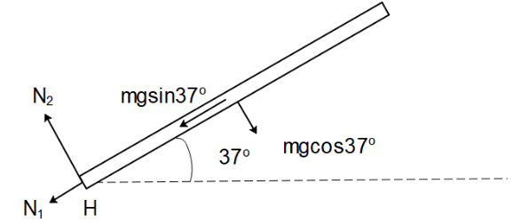
The net force that will be exerted by the hinge will be resultant of the forces that act in the direction parallel and perpendicular to the direction of the rod.
For the direction parallel to the rod, since there is no net force, we can write
⇒N1=mgsin37∘
⇒N1=53mg
For the direction perpendicular of the rod, since the pseudo force associated with the acceleration of the rod will act in the direction of N2 we can write the equation of force as
⇒mgcos(37∘)−N2=ma .
Here a is the linear acceleration of the rod that acts on the centre of mass of the rod so we can relate the linear and angular momentum of the rod as a=2αl=53g . So,
⇒54mg−N2=53mg
This gives us,
⇒N2=5mg
The net force exerted by the hinge on the rod is
⇒N=N12+N22
⇒N=(53mg)2+(51mg)2
On simplifying, we get
⇒N=105mg .
Note
While calculating the torque and the linear acceleration of the rod, we must represent them as acting on the centre of mass of the rod. While making the free body diagram of the rod, it is beneficial to us to make the components of force in the direction parallel and perpendicular to the rod since it will simplify our visualization and calculation.