Question
Question: A square metal wire loop of side 10cm and resistances \(1\Omega \) is moved with constant velocity \...
A square metal wire loop of side 10cm and resistances 1Ω is moved with constant velocity v0 in a uniform magnetic field of induction B=2Wbm−2, as shown in figure. The magnetic field lines are perpendicular to the plane of loop and directed into the paper. The loop is connected to the network of resistances, each of value 3Ω. The resistance of the lead wires OS and PQ is negligible. What should be the speed of the loop so as to have a steady current of 1mA in the loop?
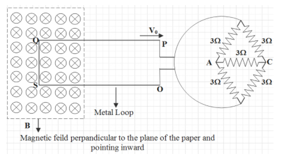
A)2ms−1B)2cms−1C)10ms−1D)20ms−1
Solution
To find the speed of the loop, initially we need to calculate the effective resistance of the network of resistances using the concept of Wheatstone bridge. Then, we will apply the formulae of induced emf and ohm’s law using the given data from the question and the calculated effective resistance to find the speed of the loop.
Formula used:
!!′!! s law, V=IR Induced emf, e=BvlOhm
Complete step by step answer:
Firstly, we will take a look into the network of resistances given in the diagram and calculate the effective resistance.
Here, the figure looks like a Wheatstone bridge. It is an electrical circuit which is used to measure the unknown resistance of any one resistor. The voltage across both the individual series connections are equal. If we closely observe the figure, it looks like there are two legs which individually have two resistors connected in series, and are connected to parallel each other.
In a Wheatstone bridge, we ignore the resistance of the bridge. So, the resistance 3Ω of the wire connected to the bridge will be removed. So the network will look like,
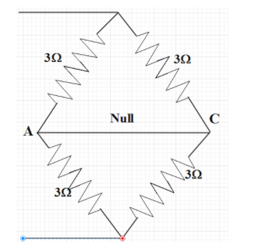
So, the effective resistance of each individual half of the network is 3+3=6Ω (as they are connected in series).
Now, these both effective resistances of 6Ω are connected in parallel to each other. Then, the effective resistance of the whole circuit will be,
R′1=61+61⇒R′=3Ω
It is also given that the metal wire has a resistance of 1Ω and it is connected in series with the network of resistances. So, the resistance of the entire loop will become,
R=1Ω+3Ω=4Ω
Now, if magnetic flux in a coil is changed for any cause, a voltage will be developed inside the circuit. This is called induced emf and it is stated by faraday’s law.
We know, induced emf is given by the equation,
e=Bvl
According to ohm’s law, voltage in a circuit is given by,
V=IR
The induced emf in the circuit will be equal to this voltage. That is,
Bvl=IR
Now, we can find the speed of the loop to have a steady current could be found from this expression.
Bvl=IR
Where, B is the magnetic field, v is the speed of the loop, l is the wire, I is the current through the circuit and R is the effective resistance.
Bvl=IR⇒v=BlIR⇒v=2Wbm−2×0.1m1×10−3A×4Ω=0.02ms−1∴v=2cms−1
So, the velocity of the loop to have a steady current of 1mA is found to be 2cms−1. Therefore, option B is correct.
Note:
In order to answer this type of question, the key is to know the concepts of solving effective resistance using a Wheatstone bridge. The effective resistance of two resistances connected in series is given by, R=R1+R2 and parallel is given by R1=R11+R21. Equating voltage from ohm’s law to the induced emf is a vital step in solving this problem. Due to moving the loop with a speed in this case an emf is formed which is nothing but the voltage that causes current flowing in the loop.