Question
Question: A square loop, carrying a steady current \(I\), is placed in a horizontal plane near a long straight...
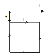
A square loop, carrying a steady current I, is placed in a horizontal plane near a long straight conductor carrying a steady current I1 at a distance d from the conductor as shown in the figure. The loop will experience
A. A net repulsive force away from the conductor
B. A net torque acting upward perpendicular to the horizontal plane
C. A net torque acting downwards normal to the horizontal plane
D. A net attractive force towards the conductor
Solution
When a current is flowing through a conductor a magnetic force is produced around it. The direction of the magnetic field and the force generated due to the conductor depends on the direction of the current flowing in it. Every external material kept in the field Experience an attractive and repulsive force (this depends on the direction of experienced force)
Formula Used:
Magnetic field due to the straight current-carrying conductor is B=2πrμ0I the force produced by a conductor is F=I(l×B)
Complete step-by-step solution
The situation given in the question can be more illustratively explained by the diagram given below,
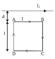
If we consider each side of the square loop. The forces experienced by the sides AD and BC due to the straight current-carrying conductor will nullify each other. This is due to the reason that both sides are at the same distance from the external conductor and the current flowing through these sides is anti-parallel to each other.
FAD=−FBC⇒FAD+FBC=0......(1)
But the force on side CD, FCD will be greater than FAD.
The magnetic force experienced by the side AB is given as,
BAB=2πdμ0II1
So the force experienced by the side AB will be given as,
FAB=I(l×B)FAB=I(lBsinθ)
As the angle between the length and the magnetic field is 2π
FAB=I1l2πdμII1......(2)
The magnetic field due to the side CD is given as,
BCD=2π(d+l)μ0II1
Similarly, the force experienced by the side CD will be,
FCD=I1l2π(d+l)μ0II1.....(3)
From equation (3) and (2) we say that both the forces are positive and will be attracted towards the straight wire so the square loop will be attracting towards the straight wire.
Thus, the correct option which stands for the true statement for the conductor's setup shown in the circuit is Option D.
Note: The direction of the force is perpendicular to the direction of the electric field and the magnetic field produced around a current-carrying conductor. The direction of the magnetic field line for a straight current-carrying conductor can be given by the right-hand thumb rule. The thumb shows the direction of the current and the curled fingers give the direction of the magnetic field lines.