Question
Question: A square loop, carrying a steady current \(I\), is placed in a horizontal plane near a long straight...
A square loop, carrying a steady current I, is placed in a horizontal plane near a long straight conductor carrying a steady current I1, at a distance of d from the conductor as shown in the figure. The loop will experience:
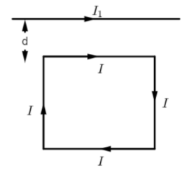
A. A net repulsive force away from the conductor
B. A net torque acting upward perpendicular to the horizontal plane
C. A net torque acting downward normal to the horizontal plane
D. A net attractive force towards the conductor
Solution
We know that a current carrying conductor produces a magnetic field which exerts a force on another parallelly aligned current carrying conductor.
From here on, we treat each side of the loop as a separate current carrying wire.
Using the right hand rule, determine the direction of the forces exerted on each side of the loop. Then, using a relation between the force exerted on a side of the loop and the distance between the wire and the side of the loop, determine the magnitude of the force experienced by each side of the loop.
Finally determine the direction in which the square loop moves under the influence of the resultant force, and narrow down on one of the options accordingly.
Formula Used:
Force exerted per unit length between two parallel current carrying conductors P and Q: F=B×I2=2πdμ0I1I2, where B is the magnetic field of P that exerts the force on Q, I2 is the current flowing through Q, I1 is the current flowing through P, and d is the distance between the two conductors, and μ0 is the magnetic permeability.
Complete step by step answer:
Let us begin with the foundation that a current carrying conductor produces a magnetic field.
We see that the magnetic field produced by the straight conductor will exert a force on the square loop. But, since the vertical sides of the loop are at the same distance from the straight conductor, the force experienced by the vertical sides on the loop will be equal in magnitude but opposite in direction, which we can deduce from the right hand rule. Therefore,
F4=−F2, so they balance each other out and the square loop remains uninfluenced due to these forces.
However, the horizontal sides of the loop are at different distances from the straight conductor. So they will not experience the same magnitude of force. Let us now dive into obtaining a relation to find the force exerted by the straight conductor of the horizontal sides of the loop. 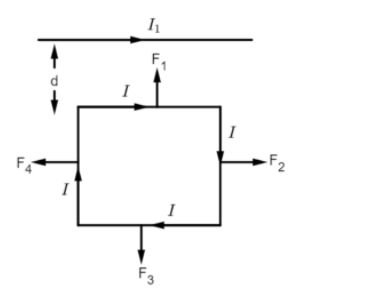
We have the distance between the straight conductor and the upper horizontal side to be d. Let the distance between the straight conductor and the lower horizontal side be (d+l), where l is the length of the side of the square.
The magnetic field produced by the straight conductor at distance d: B=2πdμ0I1
Therefore, the force exerted per unit length on the upper horizontal side by field B: F1=B×I=2πdμ0I1I
The magnetic field produced by the straight conductor at distance (d+l): B=2π(d+l)μ0I1
Therefore, the force exerted per unit length on the lower horizontal side by field B: F3=B×I=−2π(d+l)μ0I1I
From the above expressions, we can deduce that force experienced F∝distance1, where the distance is between the straight conductor and the side of the loop.
Therefore, since (d+l)>d ⇒F3 <F1.
Therefore, F1 will pull the loop closer to the straight conductor as there will be a net attractive force towards the conductor, and the direction can be verified using the right hand rule.
The correct option would thus be D. A net attractive force towards the conductor.
Note:
Do not get confused between the right hand rule and the right hand thumb rule.
The right hand rule involves using three fingers aligned in perpendicular directions to each other, where the magnetic force (indicated by thumb), the moving charge or current (indicated by index finger) and the magnetic field direction (indicated by the middle finger) can be determined.
The right hand “thumb” rule involves a closed fist, with the upright thumb pointing in the direction of current flow and the fist representing the direction of the magnetic field lines.
It is utilizing only these two tools that we have found the necessary directional information in our problem.