Question
Question: A source of alternating emf of 220V and 50Hz is connected in series with a resistance of 200\(\Omega...
A source of alternating emf of 220V and 50Hz is connected in series with a resistance of 200Ω, an inductance of 100mH and a capacitance of 30mF. Does the current lead or lag the voltage and what angle?
Solution
In an AC circuit, the current lags the voltage when XL > XC. The current leads the voltage when XL < XC. Find XL and XC by the using the formulas XL=ωL and XC=ωC1. Then check the relation between the two. To find the phase difference use tanα=VRVL−VC.
Formula used:
XL=ωL
XC=ωC1
tanα=VRVL−VC
Complete step-by-step answer:
In an AC circuit, the voltage (potential difference) across the components in the circuit and the current flowing in the circuit are treated as vectors. The phase difference between the current and the voltage across the respective component is the angle between the current vector and the voltage vector of the component.
Since the voltage across the resistance and the current are always in phase, the vectors of voltage of resistance (VR) and current (i) are parallel.
There is a phase difference of +2π between the inductor voltage and the current. That is the inductor voltage leads the current by a phase of 2π.
Therefore, the vector of inductor voltage (VL) is at an angle of +2π from the current vector.
There is a phase difference of −2π between the capacitor voltage and the current. That is the capacitor voltage lags behind the current by a phase of 2π.
Therefore, the vector of capacitor voltage (Vc) is at an angle of −2π from the current vector.
The entire can be summarised with the help of the diagram given below.
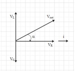
Hence, Vnet=VR2+(VL−Vc)2.
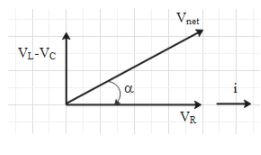
Angle α is the phase difference between the emf of the source (i.e. Vnet) and current in the circuit.
Here, VR=iR, where is the resistance.
VL=iXL, where XL is inductive reactance. And XL=ωL, ω is the angular frequency of the source and L is the inductance.
⇒VL=iωL
VC=iXC, where XC is capacitive reactance. And XC=ωC1, C is the capacitance.
⇒VC=ωCi
From the figure we can make out that if VL > VC, then Vnet will be in the first quadrant and phase angle αwill be positive. This means that the current lags the voltage.
Now, VL > VC ⇒iXL > iXC
⇒XL > XC
Therefore, if XL > XC, the current lags the voltage.
If VL < VC, then Vnet will be in the fourth quadrant and phase angle αwill be negative. This means that the current leads the voltage.
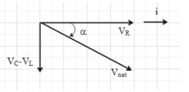
Therefore, if XL < XC, the current leads the voltage.
Let us check the relation between XL and XC for the given circuit.
It is given that the capacitance C=30mF, inductance L=100mF and frequency f=50Hz.
Let use the formula ω=2πf to find angular frequency ω.
Therefore, ω=2π(50)=100πs−1.
Let us calculate XL and XC.
XL=ωL=100π×100×10−3=10πΩ
XC=ωC1=100π×30×10−31=3π1Ω
Therefore, XL > XC.
This means that current lags the voltage.
Let them find the phase difference i.e. α.
For this look at the second figure. Here, tanα=VRVL−VC
⇒tanα=iRiXL−iXC
⇒tanα=RXL−XC
Substitute the values of XL, XC and R in the above equation.
⇒tanα=20010π−3π1=0.15
⇒α=tan−10.15
Note: Let us understand what it means when we say that the current is leading the source voltage or the current is lagging the source voltage.
When the current is leading the voltage, the current will reach its maximum value before the voltage reaches its maximum value.
When the current is lagging the voltage, the voltage will reach its maximum value before the current reaches its maximum value.