Question
Question: A signal of \[20mV\] is applied to a common emitter amplifier circuit. Due to this, the change in ba...
A signal of 20mV is applied to a common emitter amplifier circuit. Due to this, the change in base current and the change in collector current are 20μA and 2mA. The load resistance is 10kΩ , transconductance is:
A) 0.1Ω−1
B) 0.2Ω−1
C) 10Ω−1
D) None of these
Solution
In this question, we have the change in collector current ΔIC and a signal which is added to the base-emitter voltage ΔVBE. We can use gm=ΔVBEΔICto find the transconductance gm of the common emitter amplifier circuit.
Complete step by step solution:
According to the question, a signal of 20mV is applied to a common emitter amplifier circuit which means 20mV is added to the base-emitter voltage(ΔVBE). The load resistance RL in the common emitter amplifier circuit is 10kΩ. The change in base current ΔIB is 20μA and the change in collector current ΔIC is 2mA.
We know that if ΔVBE is bas-emitter voltage and ΔIC is the collector current, then the transconductance gm of the common emitter amplifier circuit is given as-
gm=ΔVBEΔIC
Now, putting the values of ΔIC=2mA and ΔVBE=20mV in the equation, we get-
gm=20mV2mA ⇒gm=101Ω−1 ⇒gm=0.1Ω−1
Therefore, the transconductance of the common emitter amplifier circuit is 0.1Ω−1.
Hence, option A is correct.
Additional Information:
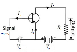
Above diagram shows a common emitter transistor. In this transistor, an emitter is common in both input circuit and output circuit. The base and emitter make the input circuit. The collector and the emitter make the output circuit. The input voltage is known as base-emitter voltage ΔVBE and the output voltage is known as emitter-collector voltage ΔVCE. We can get the output current at the load resistance RL.
Note: In this question, two types of change in current are given. We can calculate transconductance by using ΔIC and ΔVBE. ΔIB is not used in the calculation of transconductance. ΔIB is used with ΔIC to calculate the current gain of the circuit. The unit of the transconductance is always Ω−1.